
Thanks go out to N3IBX for the tour of his collection
I have some good memories of the late 50s and 60s listening to the classic boat anchors. The 32V, the BC-610, DX100, and the Viking 2 ruled the bands back then. I never had the money for those as a high school kid. I finally did trade up to a Viking 2, which is still my rig of choice. The Viking 2 also was available as a Civil Defense model that transmits on all frequencies from 1.7 to 30 MC continuous. Great for Pirate Radio. And the CD version brings back memories of the good old days when school kids were sent home to hide under their bed in the event of nuclear war. You could even get a Gonset 2 meter AM transceiver for CD use. The Collins 32V transmits outside the ham bands, making it ideal for MARS operation in that era. I have done some work on these radios as the "pit crew" of a friend. For the big repairs of Collins gear, I recommend the following resources. There is no substitute for experience when it comes to equipment of this complexity. A good stock of the specialized unobtainium parts is essential.
The 32V has such a following that some have made a career of its restoration:
http://www.collinsradio.org/howard-mills/
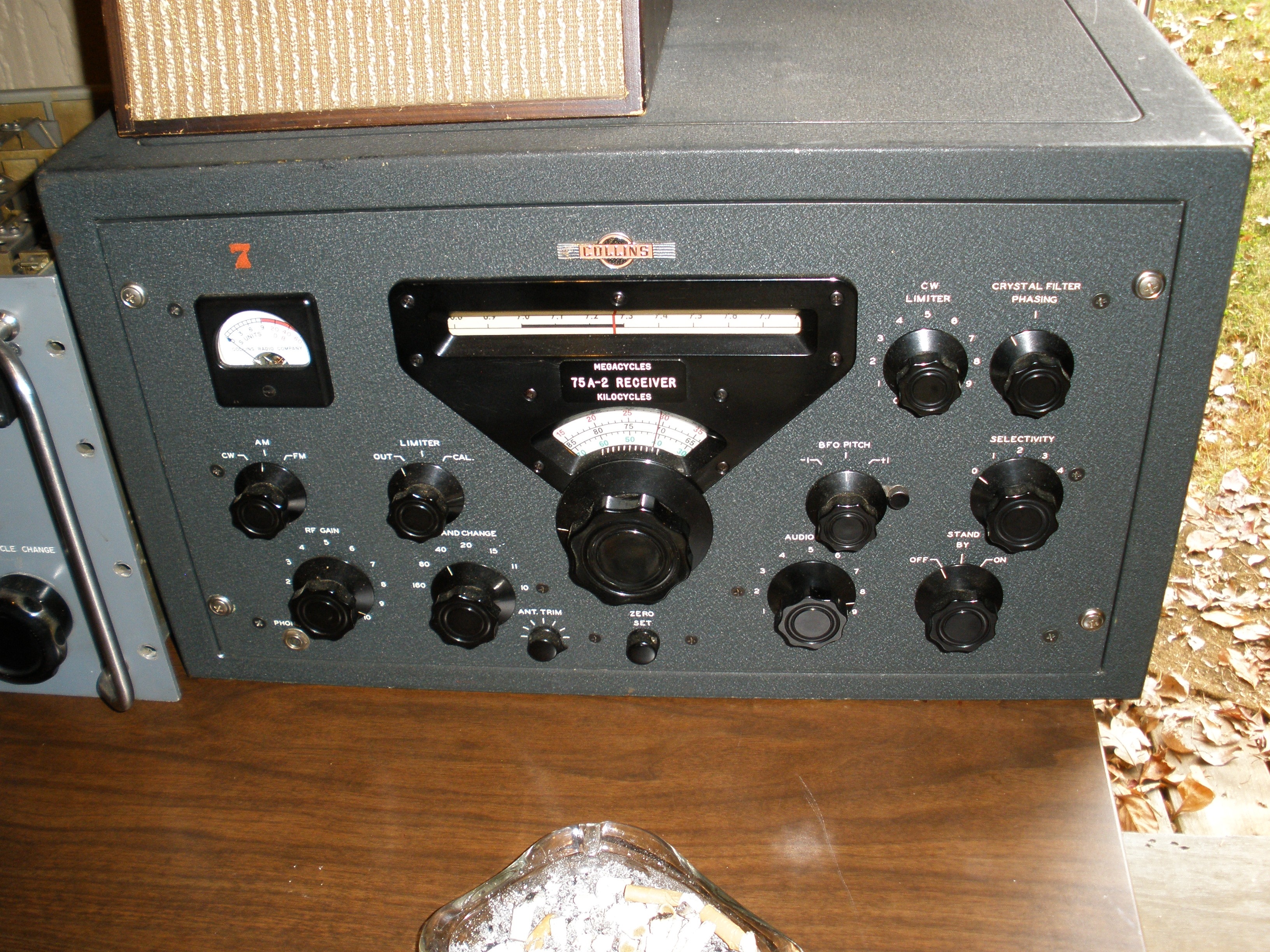
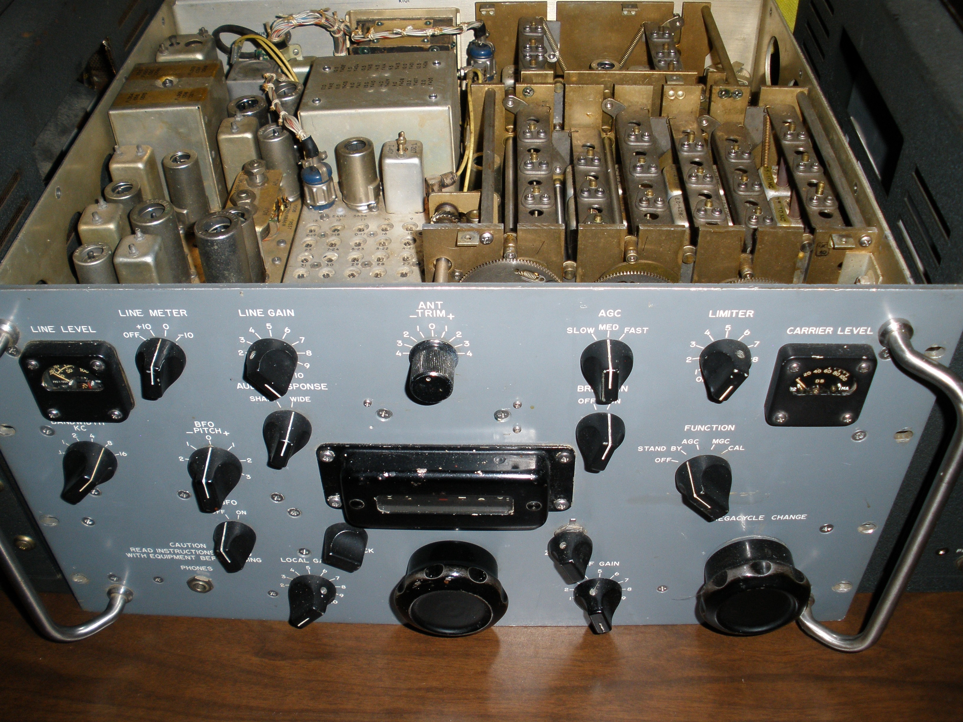
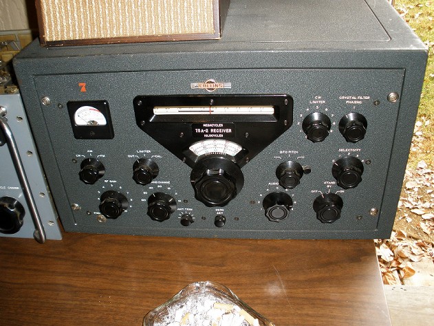
The R390 pictured above is often paired up with the 32V. Another person does restoration of that receiver:
http://feltondesign.com/index.html
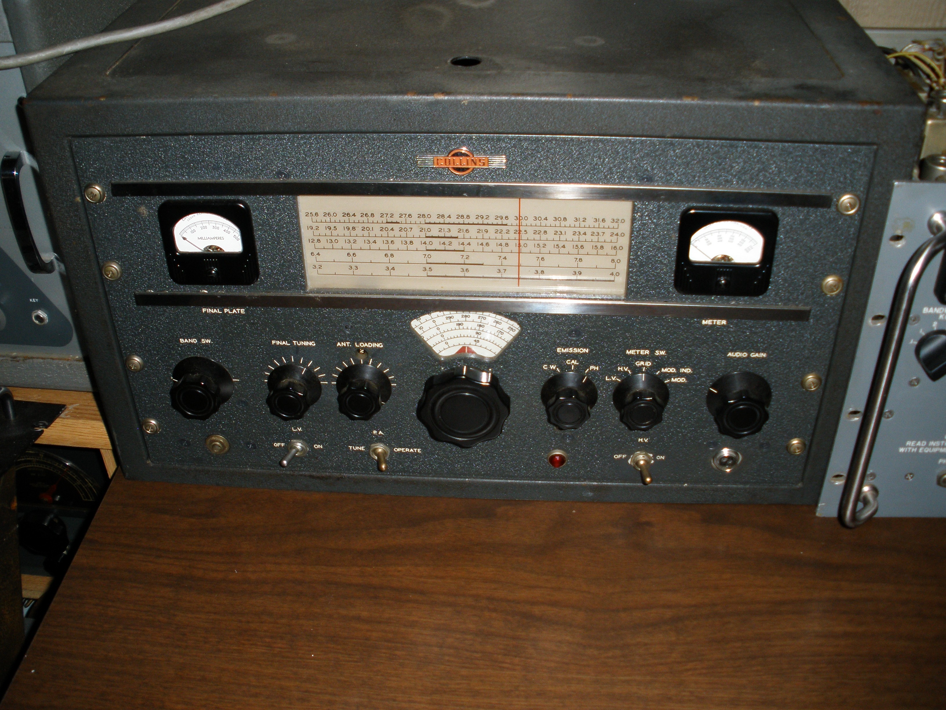
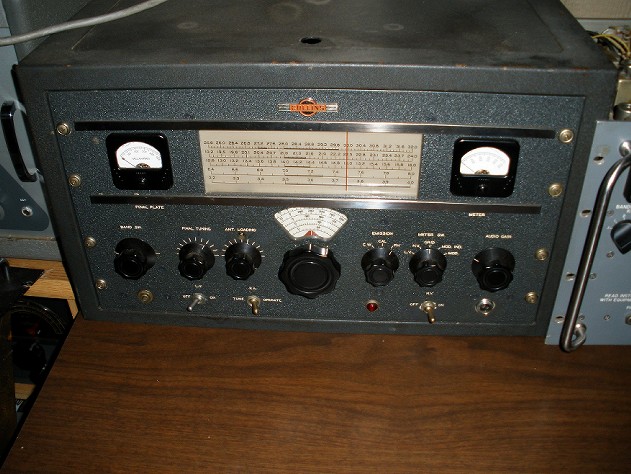
The 32V had innovative technology, which included a Permability Tuned VFO (PTO) with amazing frequency resolution and accuracy and a tracking gang tuned exciter for quicker QSY. This radio came with some impressive specs for the time:
PA Plate Power Input:
The nominal rated power input of the 32V-3 is 120 watts on phone and 150 watts CW.
Audio Distortion:
Audio distortion is less than 8% at 90% modulation with a 1000 cps input frequency.
Frequency Response:
Within 2 db from 200-3000 cps.
There are audio mods from Timtron and others that improve distortion and frequency response, and I will make no effort to reinvent that wheel. The mods are not that hard to do, since once the rig is out of the cabinet, the underside of the modulator chassis is easily accessible from the right hand side.
Complete 32V3 manual at:
http://www.qsl.net/wa5bxo/32v3/
The biggest difference between the 32V3 and the 32V2 is the addition of the metal cage around the RF section and implementation of series "loading" capacitors for C406, 407, 408 in the Pi-L final output tank circuit. This was an attempt to address chronic band switch and capacitor failure. More on this later.
Complete 32V2 manual at:
http://www.jptronics.org/radios/Collins/32V/32v2.manual.1.pdf
Note especially the addendum dated 2-1-50 and 1-25-51 regarding changing the taps on the L section coil, L404 and the modification to parts list of L section "loading" capacitors C406, C407, and C408.
Stuff your Collins manual and fans did not tell you about the 32V:
This part of my page deals with the shortcomings and cautions. Call it the care and feeding of the 32V if you like.
All this having been said, I am probably notorious for calling it the way I see it. I do not intend to depart from that here with a whitewash out of respect for a venerated icon of ham radio history. If you are a Collins fan, do not take any of this as a slam job on the rig. Like all vintage equipment, there are things you have to take into account. As I said before, I did repairs for a friend, and had the opportunity to own a 32V and passed it up due to that experience. For those of you who love Harleys and know how to maintain them, it takes love and dedication to keep the relationship going; same thing is true for the Collins 32V. So, as with all equipment from this era, there were certain quirks you had to know about to survive.
First, be aware of the two pin microphone connector that the high voltage PTT line is connected to. If you plug a mike in with the radio turned on, you could fry the mike element, especially if you have one of the electret condenser elements from W2IHY. You can obtain one from:
http://members.bellatlantic.net/~vze3rys4/D104Replacement/
This is not a slam of his mike element. It sounds real nice. But if you plug the mike connector in with the power on, the high voltage for the relay coil passes through the mike element since the ground is missing until you screw on the grounding shell. This also happens with the Johnson Valiant and other radios that employ this 2 pin connector. This is why I replace the stock 2 pin connector that does not have good springs in the female chassis connector anyway with the 4 pin mike connector that is popular on ham and CB equipment. It has good connections that also can provide for a reliable ground. It is available at Radio Shack stores with the parts drawers. I do not think the voltage surge is very good for the stock D104 element either.
You probably do not want to change the front panel connector to a 4 pin on a collectible radio of this value. Just do not change mikes with the power on, or you might regret it.
Second, there are reports of LV transformer failure.
There is one article on how to replace it. Electric Radio #224 page 30,
http://www.wd8das.net/ERrectifier.pdf
I always have to second guess this type of thing, not having had this occur. First, never replace fuses with a larger size or time delay slow blow if the original is a standard quick blow. You wouldn't make a rookie mistake like that with a collectible radio, would you? You did do an inventory of all the fuses of the gear in your station and test bench to have the correct spares on hand, right? And you replaced the electrolytic filter capacitors as a preventative measure with conservative voltage rating, correct?
So the probable cause I am pointing to is the excessive heat generated by running equipment rated for 115 VAC nominal on modern AC lines which often soar to 130 VAC. You can obtain a 3 Amp or larger 12 Volt AC transformer from Radio Shack or your junk box and connect it in series with the LV transformer primary. It is not that big, and somewhere there is room for it inside the cabinet. This is particularly important if you leave the rig on while you leave the shack for an extended period like a meal. I plan to post how to connect up a "bucking" transformer on this site, to make the procedure clear. Reducing the LV strain which is continuous will fix this problem. Doing the same for the HV transformer is harder, since the current draw is much larger. But the load is only on when you are transmitting. If you allow sufficient air circulation and/or install a ventilation fan (always a good idea to reduce drift and component stress) it should keep you out of trouble. A better idea is to use the 600 V to 700 V switch on the back of the rig in the lower position. You do not get a noticeable rise in S meter readings at the far end by running the rig hotter.
Third, the CW keying waveform has ringing and variations in it.
The HV power supply has a resonating capacitor across the swinging choke to improve regulation. It works OK on AM, as the load is more constant. The transients caused by full power to no power input on CW are more than the circuit can compensate for. W8JI has some discussion of the resonating capacitor for another radio, but the material is applicable to the 32V. Most folks have a 32V for AM operation anyway. I did not ever attempt a fix for this. It looks real ugly on a monitor scope, but does not seem to generate many complaints from listeners on CW. Maybe not a big deal.....
Fourth, the VFO tube is often not tested during a maintenance cycle.
I noticed that sometimes the VR tube would not light correctly and the rig would be slow keying up. I tested all tubes and hoped I would find an easy fix. But rather than digging into the innards further, I decided to test the 6SJ7 oscillator. I dented the cover over the tube with a pair of vise grips in the removal, the glue used before was so strong. When I reinstalled the replacement, I used a very thin film of bathtub seal for the gasket, since this seemed to work well for the thermostat on a car. I was amazed when I put the 6SJ7 in the tube tester. No meter movement on emission or transconductance test at all. I had to try a new in box tube in the tube tester before I was sure that the tester was not bad. It is a credit to Collins engineering that it still worked with a tube that weak. Object lesson: do not neglect to test the VFO tube during routine maintenance. Also, be sure to observe the procedure for reconditioning the dessicant crystals to keep the VFO stable.
Fifth, the cover for the feed through capacitors where the AC line enters the rig can short to the metal cover.
I routinely install a heavy plastic insulator glued to the metal cover during routine maintenance of a 32V. This prevents fuse blowing and electric shock. While you are at it, install a 3 wire grounding cord. There is a condition where the HV indicator lamp can cause a shock problem by shorting to the case. The three wire plug affords some protection in this instance by tripping the house circuit breaker.
Sixth, some of the tubes are getting scarce.
The 4D32 final is still available as WW2 surplus, but once they are gone, they are gone forever. It was used as a radar tube, and procurement for spares flooded the surplus market temporarily.
The 7C5 exciter tube seems to be still available, but you better stock up. It is a loktal tube. A loktal tube has a center metal pin that grounds the metal skirt on the bottom of the tube and prevents the tube from falling out of the socket when flying upside down with lots of vibration. Seriously! Many of the post war consumer FM radios used loktals because they were cheap surplus, and the standard octal tubes would not work well at 50 MC and 100 MC. WERS era radios for emergency communications on 5 and 2.5 meters often removed the socket from the bottom of the tube and soldered directly to the wires coming out of the glass. You say your Harvey Wells bandmaster with the 807 in the final worked just fine on 2 meters? Really? (The first FM band before TV was near 50 MC, and it was moved to 100 MC. Somehow our 5 meter band was changed to 6 meters and we moved from 2.5 to 2 meters, in the deal to create TV.) The 7C5 specs are similar to the 6V6. I believe Collins selected the 7C5 due to its shorter internal leads and lower inductance for better RF performance. Those of us who have built simple transmitters using the 6V6 or 6L6 realize that stability on higher frequencies like 20, 15, and 10 meters are a real challenge. So there is probably no proper substitute for the 7C5. It is sad these tubes did not catch on better, but the so called 7 and 9 pin miniatures took over. The acorn tubes died out too. For a fascinating history of loktal and acorn tubes see:
http://www.dos4ever.com/EF50/EF50.html
Early radar systems employing these tubes literally turned the tide in the battle for Britain. This quote about government procurement methods comes from the above article. Sound familiar for our time?
The Germans clearly concentrated all the secret projects in their own electronic companies, and used Philips mainly for the production of standard radio tubes and light-bulbs. And even that production was seriously sabotaged, not only by the Philips employees but also the Germans themselves:
Auto-sabotage in the German Organization: the German system of allocation and control was, as the Philips management said, the most effective sabotage agency known to them. The proliferation of papers, the failure to devolve responsibilities, the refusal to exercise initiative,the appointment of technical incompetent supervisory and progressing officers, and the concentration of attention on clearing the documents rather than the materials, sufficed in themselves to impede production. Exploited by an expert and ingenious body of non-cooperators,this system lent itself to a double frustration. Well, Professor Peabody, enough with the WABAC Machine. I just want to fix my 32V. OK then.
Seventh, the exciter section is extremely compact, and the ganged tuning to the VFO is a watchmakers dream. If you are up to the challenge, go ahead. Otherwise, pay one of the experts I listed at the beginning of the article. If you service the exciter, the spurious signal traps C147 & C149 should be checked and will probably require adjustment as described in section 5.3.3 of the 32V3 manual. These reduce spurs that appear to fall within the ham bands, but you should be aware of them. Here is W1UJR's experience with the exciter gang tuning:
http://w1ujr.net/collins_32v3.htm
Eighth, the final tank circuit components are subject to failure.
Collins service bulletin:
http://collinsradio.org/archives/manuals/32V-2_SB_1.pdf
I am not the only one that has experienced this problem:
http://www.w1ujr.net/zorch_gods.htm
Here is a complete tear down and restoration that discusses this problem briefly:
http://www.km5tz.com/32V2.htm
There is a reason that many pages in the instruction manual and the supplement describing the Collins 80 meter broad band dipole (also in popular hand books of that era) insist on non reactive low SWR loads for the 32V. Early manuals for the 32V2 claim 25 to 600 ohm matching range. I am skeptical about any more than 100 ohms completely resistive, for a 2:1 SWR. In fact, paragraph 2.3.7 of the 32V3 manual calls for a FLAT (non reactive) 52 or 72 ohm load. It is essential to do all final loading and antenna tuner adjustments with the 32V switch set to TUNE not OPERATE. Even then, a device like the MFJ-212 will allow you to adjust your transmatch without ever using the 32V outside its specified load ratings. You can tune the 32V into a 50 ohm resistive dummy load, and use the reciever and noise bridge to adjust the transmatch. Other than the TUNE OPERATE switch, there is no way to reduce power to safe levels on the 32V during adjustments. There is no DRIVE control on the 32V, nor is there a clamp tube to limit the input power during loss of drive. The drive is magically adjusted in the exciter tuning, which tracks the VFO.
Using the rear panel high voltage 600 or 700 volt switch in the lower position will not significantly reduce the S meter reading on the other end. But it might be just enough to save the Pi-L components. Only you can decide if it is worth the risk to run it at the high tap. Keep in mind that the higher line voltages of today may boost the voltage at the high tap to bigger values than originally anticipated by the original designers. The low tap with modern voltages may be an in between HV value that holds it all together.
CAUTION: NEVER, EVER, EVER adjust the loading control during transmission in such a way that the numbers rotate inside the little hole on the front panel, indicating that the loading switch is changing positions. You are changing the loading switch on a high Q circuit. It is similar to changing the band switch on your big amplifier while transmitting. You would not do that, would you? Remember a 100 watt AM rig is running 400 watts PEP while modulating. It is best to tune up in TUNE only. Use CW mode to check the final plate current. Let up on the key, then make an adjustment to the loading control, to prevent the failure mode from occurring. Once you have all the currents adjusted to spec, turn OFF the PLATE switch and switch to AM mode. Then and only then use the PTT on the mike to transmit. DO NOT EVER switch modes while the PLATE switch is ON or you may damage the mode switch.
This is not meant to be insulting. Many hams that did not grow up in the tube era are used to modern radios with lots of built in protection circuits like an Alpha amplifier. This is why you find people bellyaching now about rigs and amps that do not auto tune at more than 3:1 SWR. If you understand the fundamentals, you do not just blindly follow folklore that may be misleading. That is why I discuss the WHY as well as the HOW.
Collins admits this is a problem in the service supplement listed at the beginning of this article, changing the L section coil taps for 10 meters and changing the capacitors C406, C407, and C408. Eham reviews notes problems with this circuitry as well, so it is not just me saying it. The problem occurs if the load gets outside a very narrow range of SWR. This can occur with bad or intermittent antenna connections. This also can happen when adjusting transmatches. CAUTION: NEVER, EVER, EVER ADJUST THE ROLLER INDUCTOR AT FULL POWER ON ANY TRANSMATCH. It is the exact same thing as turning the inductance switch! Besides the hazard of intermittent contacts, the pitting from arcs only exacerbates the problem as the pitting breeds itself. The only touch up allowed is on the capacitors; use CW with the key UP to shut off the carrier when turning the roller inductor knob. This may be difficult to do with the 32V, since it does not have a DRIVE control like other rigs of this vintage. In a case I observed, the transmatch (Heathkit SA2060) had intermittent contacts on the roller inductor due to incorrect assembly by the original builder. I cover this in a separate article. But the Ten Tec 238 this owner also had gave problems too. Ditto on the don't change the roller inductor during full power transmit for the Ten Tec as well. The Johnson Matchbox he had tuned very sharply and during tuneup really stressed the 32V as well. Yet another argument for broad band dipoles as recommend in the Collins manual. I discuss one such antenna on this page which should do the phone band with NO tuner required at all, even for the 32V. Mine is inspired by an article in Electric Radio by Chuck Felton, referenced as a resource at the beginning of this 32V write up.
Here is Collins original broad band antenna design:
http://www.qsl.net/wa5bxo/32v3/
OK so you fixed the taps on the 10 meter coil per the update. Does the capacitor fix do the rest of the job? I think that it may have addressed the VOLTAGE rating problem. But it did not increase the CURRENT rating of the fixed mica capacitors. Parallel capacitors would have passed more current. Individual capacitors with sufficient ratings probably were not cost effective or physically small enough to fit in the space allowed. The SWR causes heating and premature failure. See the failure analysis one person did by cutting apart a failed jumbo postage stamp mica capacitor in this circuit.
The worst part of it is that once the capacitors fail, they cause even more current to flow in the loading switch, or arcing due to voltage getting too high because once the capacitor fails, because the tank circuit is mistuned at full output. It either puts carbon tracks on the ceramic that cannot be removed or melts the contact off the switch. The switch is a special part that is not commonly available. So if you wreck it, the rig is hosed.
There is only one way to restore operation if you cannot get the unobtainium loading switch. You can eliminate the original Pi-L circuit and go to a standard Pi network. This will require changing the wire from the large 80 meter tank coil to eliminate about 6 turns. You will need a different fixed capacitor for the 80 meter plate tuning shunt to get back to resonance from the removed turned. You will need to completely wire around the L network coil. You can find other contacts on the burned out switch wafer that will sort of work for the fixed capacitors or use one of the binary coded decimal switches used on the DX100 or Valiant loading switch. The reason this works is that the voltage and current ratings required on the output of a standard Pi network are much easier to meet. In the original Pi-L configuration, the capacitors and switch wafer were operating at a higher impedance point, more like 600 ohms. The circuit Q was very high at that point, especially on 10 meters, which is why they changed the 10 meter tap in the service bulletin.
IMPORTANT: if you do this as a permanent repair, it is a significant design change, and the harmonic suppression of the 32V will be seriously compromised. You can use an outboard harmonic filter (NOT a TVI filter) that suppresses the second harmonic and higher from the modified tank circuit, one for EACH BAND.
You can use a Johnson KW transmatch. But I recommend you use it with a MFJ matchmaker noise bridge and adjust the transmatch in receive mode only to protect the 32V.
You can also use a tuner like the home brew one I describe on this web page. It is a mirror of the popular Murch design. In other words, it is a variable LOW PASS design, using an input inductor, a capacitor to ground, and another inductor to connect to the antenna. This is a more expensive design since it uses two roller inductors instead of one. I built mine deliberately to address the harmonic radiation from vintage rigs attached to multiband antennas. I will present the complete design and construction with photos on this site when I can get to it.
UPDATE 1/31/2024: I just got off the air with Don KD2FO who came up with a clever solution to the loading capacitor problem. It is similar to the capacitor that was offered as a kit and later incorporated in the DX-100B. The scheme of a small variable capacitor and switched fixed mica capacitors can be replaced with a standard 3 gang broadcast band variable capacitor. This should be mounted in place of the small air varable cap. The switch for loading and its associated capacitors are no longer needed. This repair eliminates the hassle of never rotating the switch during tune up, since its OK to change capacitor settings til you get it tuned properly. It also preserves the Pi-L network and superior harmonic reduction. My only caution would be to try to find a 3 gang air variable with fairly wide spacing. This capacitor is located at a point where the impedance (and therefore the voltage) is higher than at the 50 ohm output of the transmitter.
WOW MY HEAD IS GONNA EXPLODE.....
OK, just one more thing. The jungle relay. That's what I call it, since everything runs through it, and the schematic is a maze of traces in and out. Get copies made of the schematic and fine point colored high lighters and settle in for a day or more. To protect it, put MOV spike catchers across the primaries of all transformers. It also protects the power supplies. Put one on the Dow Key relay coil too. When you unkey the PTT, the field in the HV transformer or Dow Key relay coil collapses. This generates arcing at the contacts of the jungle relay. An MOV absorbs the voltage spike and will prevent pitting of the contacts. Gentle, light burnishing with a fine grade tool will clean off the burrs on the contacts, but do not get carried away. For preventative maintenance, just use a strip cut from a business card.
Do I hate this rig? Heck, no! I had a lot of fun working on it. It was on my "bucket list" to play with one, and I am grateful my friend gave me a chance to work on his. I never could have afforded it.
If you like to ride a Harley, you probably will never switch to a Japanese machine. That is how you wanna roll. Likewise the 32V.
Objectively, I have had no money to spend on the hobby. I acquired the Valiant as a gift, a rescue dog. It generates a reliable easy to work on 150 watts of high quality AM as I have modified it, for a lot less money than a 32V. Even the Viking 1 and 2 will do the job well, if the awful stock audio is fixed. As I said in my article on the Johnson Pacemaker, I own a radio to operate it. Once I finish restoring it, I want to move on to a new fun project, not spend all my time under the hood tinkering.
Bottom line: For a rig to earn a spot at my operating position it must possess certain qualities. One of the non negotiable considerations for equipment of this physical size is that it must cover 160 meters. It also should be easy to work on (and once rebuilt, not be high maintenance), and not contain a lot of unobtainium parts. So the 32V did just not make the cut for me.
I hope my observations here are a worthwhile contribution to the lore on the 32V, and help you keep yours running. I tried to provide the unvarnished TRUTH and gather the collective wisdom of others on the subject in one place.
"The test of the machine is the satisfaction it gives you. There isn't any other test. If the machine produces tranquility it's right. If it disturbs you it's wrong until either the machine or your mind is changed."
|