|
Everyone has
their own solution; just because they differ does not mean that one
or more of the approaches is wrong. I appreciate them taking the time
to put their ideas out there to help others. They risk someone
disparaging their work when they do, but do it anyway. I present my
reasoning here, and the alternatives to my approach; you are free to
explore options. By explaining my methods, even if you do not do any
modifications, it may provide some ideas to begin your own work. I
hope you found something useful.
Heathkit did not observe the 6146 AM specifications in the tube manuals in either the DX100 or Apache. They ran them at CW ratings in AM phone operation, about a 40% overload. Even with heat sink plate caps and forced air cooling, this shortens the life of your tubes without a meaningful increase in S meter reading on the other end of the QSO, If you own one of these rigs, you really need to read this first foundation article! Your tubes will thank you! The 807 or 1625 modulator designs still had plenty of skrote with minimum tweaks to 100% modulate even at the over power rating 6146s. E F Johnson got it right with the Viking 2 and Valiant, even though it resulted in less advertised horsepower. The severely deficient driver in the Viking 2 can be all fixed in the driver stages. That is a project I will tackle later; see coming attractions. I have two nice Viking 2s to restore, one to go to Long Island so I can do AM from there.
Everyone wants to rip out the clipper in this rig and the Heathkit Apache. To remove the clipper circuit from the Apache, just turn the
clipper pot or unplug the 6AL5. The Apache is a poorly implemented partial lift of a very good circuit from the Terman Radio Engineering
handbook, which will be the subject of a later article, which also describes how to add 160 Meters to an Apache, keeping the correct circuit
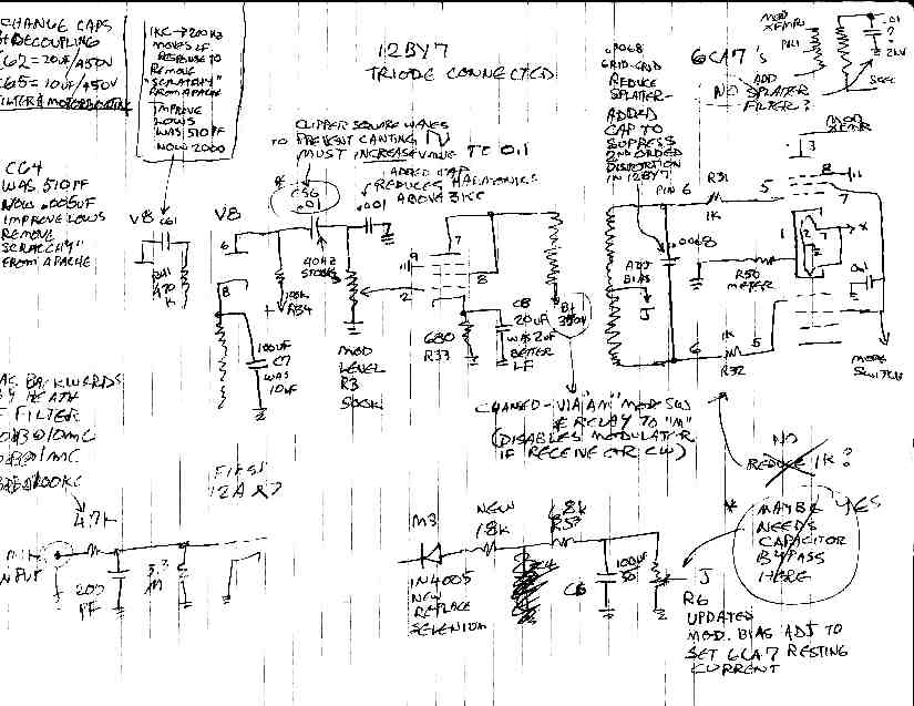
Q (something which neither the Viking 2 or DX100 do properly.) Everyone ignores the small coupling capacitor in the grid of the 12BY7 driver
in the Apache, which results in tilting of the square waves coming out of the clipper (which results in splatter!) The harmonic
distortion from a single ended driver stage also can cause splatter, which is why putting a small capacitor across the secondary of the
driver transformer to grids 6CA7s is a necessity, if you keep the original design.
http://k9sth.com/uploads/Not_so_scratchy_apache.pdf
One very serious deficiency of the Apache is the tendency to arc between the plate and screen pins on the 6CA7 modulator tubes. You will see a faint carbon track on the top and/or bottom of the tube socket and the tube itself. This commonly happens in some of the 6L6 guitar amps that use higher plate voltages. You must remove the carbon track or replace the socket. Any dampness from a basement environment will contribute to the arcing. When replacing 6CA7 tubes, I ALWAYS put "leggings" of shrink sleeve directly on the tube plate and screen pins to increase the arc path. Only 3/32 of an inch is enough to protect it. A coating of insulating paint on the tube base at the top of the pins is also important. Use corona dope, rid arc, or tool dip. Replacing the 6CA7s with 6146s eliminates the arcing problem by installing a plate cap style tube. It might be
interesting to try an "ultralinear" output stage as was
popular in hi-fi equipment. This might play well in the Apache, as
6CA7s frequently are used in this fashion. I do not know if 6146s
lend themselves to the ultralinear mode of operation. Since the
Apache uses the 6CA7 far beyond its voltage ratings, the 6146 would
be a good choice to replace the 6CA7, and the plate impedance of the
6146 might allow it to just bolt up to the existing mod transformer
in the Apache. To do it in the common configuration, you would need
screen taps (about 20% up from the B+ terminal) on each side.
However, you might be able to use resistors across each side of the
primary winding for each screen supply. This would waste some audio
power in the resistors. It would also exceed the screen voltage
rating for the 6146, unless you reduce plate supply voltage. This
would also reduce output power. There is nothing in this thread of
thought that appears useful in the Valiant without dramatic redesign
of the whole radio; it would be better to start over with a fresh
design. Distortion in the configuration I would up with is good
enough for my use. Some of the ideas in the Valiant article could work out
for you on your Apache, but that is NOT an article about the Apache.
That is another story which I may get to, along with putting the
Apache on 160 meters.
I wanted to
maintain the clipper function. You may debate the wisdom of this, as
I discuss later. It is essential to retain the excellent low
frequency response provided by this 20A14 transformer to prevent
canting of the low frequency square waves coming out of the clipper
if you wish to enjoy the full benefit of its operation. When using
low level speech clipping, it is essential to reduce excess low
frequency response in the stages preceding the clipper and get the
stages following the clipper as close to DC coupled as possible. This
criterion is generally NOT observed in transmitters of this era such
as the Apache. The Apache uses small coupling capacitors and a driver
transformer which are inadequate to use the clipper properly, causing
its "scratchy Apache" sound. The Apache clipper, which is
an exact copy of a circuit in Terman Radio Engineer's Handbook, is
not the cause of the problems at all. Heathkit's defective
implementation is the true culprit. When using the line input with
outboard audio chains, you will appreciate the 20A14, which CAN drive
the 6146Bs into full class AB2 and still have good frequency response
without running 1000V on the plates of the 6146 modulators.
Many people
remove the clipper from their rig. They lose the over modulation
protection afforded by the limiter. It is better to make the limiter
work right. My design does that. The limiter (clipper) is solid state
diodes on a small circuit board. This frees the socket used for the
6AL5 for a 6AV6 amplifier tube for impedance matching and gain and
circuit design flexibility. I found that increasing the resistance of
the pot and another resistor noticeably improved the waveform in the
limiter. While the Johnson values are the same as common handbook
circuits, I found my mine seemed to work better. Driving it hard
makes clean looking square waves. The original circuit looks terrible
and depends on later filtering to reduce that. W8JI leaves the
clipper in and recommends shorting one of the diodes with a capacitor
if you want to only limit the negative peaks and allow upward
modulation to 130%. How he achieves this upward modulation percentage
without work on the output stage to make it work in AB2 or gets low
distortion output escapes me. I felt that 3 to 6 dB of gain
compression would provide better average modulation level punch than
the asymmetrical modulation, which vintage receivers do not tolerate
well. Synchronous detection will love the upward peaks. Everyone has
their own solution; just because they differ does not mean that one
or more of the approaches is wrong. I present my reasoning here, and
the alternatives to my approach; you are free to explore options. In
practice, no one seems to complain about smaller levels of clipping.
It just prevents splatter. Once you exceed 10 dB, people do not like
the sound for casual local ragchewing, but it does help some in bad
conditions. 18 to 24 dB will likely get you a "military sound"
audio report, and the EFJ manual tells you that. Excessive use of
clipping or any nonlinear compression techniques causes
"intermodulation distortion", a gravelly sound. This
results from harmonics and mixing products between all the
fundamentals and harmonics contained in the original voice signal. I
am sure that you have heard over processed SSB stations, especially
trying for a contest mode signal. Even properly done, it gets the job
done, but not nice for rag chews. Exercise common sense and
moderation in all things. If you do not want to use the clipping
function, turn down the gain control, don't hack it out. Or use the
points indicated in my schematics to bypass the function you do not
want.
For more authoritative information on frequency range for voice communication and optimum clipping levels, consult the Radiotron Designer's Handbook. It is out of print, but you can find a copy for about $30. It is definitely a good resource.
UPDATE (1/4/2013): I have long ago sold this rig. It was one of the rigs, like the Johnson Valiant, forever caught in a period when AM was passing away and SSB was coming in, and the challenge to do both and hit a competitive price point was daunting. In the end, the result was it did neither very well. But all is not lost, if you are willing to do some work. That is the fun of restoration and improvement. I like the DX100 better than the Apache, for reasons I will make clear later.
Many of the things in the DX100 article apply to this transmitter as well. There are significant differences between the DX100 and the Apache. Here is a comparison:
PLUSES: The Apache includes switching for use of the SB10 SSB phasing exciter. The Apache features improved grid block keying for CW. The VFO tuning control is greatly improved with anti backlash gear train. There is a factory modification fan available for the Apache. The Apache provides for final neutralization (see notes though). The Apache has a clipper for better punch than the DX100 (see notes though). The Apache included a nice TUNE function to protect the finals.
MINUSES: The fan is required because the Heathkit tune up instructions incorrectly run the RF finals well above ICAS ratings. The Apache does not cover 160 meters (but can if modified). Early versions of the Apache did not have contacts on the CW/AM/SSB switch for properly connecting the neutralization when the SB10 is not engaged. The modulator tubes are 6CA7s. The Dyna Stereo 70 delivered 35 watts per channel of high quality audio from a pair of 6CA7s per channel. The Apache drives them well beyond their ratings and gets pretty bad sound in stock form. The modulator sockets arc between the screen and plate pins. The new clipper as implemented does not work right (but can be fixed). The knobs come in a chrome plated version and an aluminum version. If you do not properly ground the rig or have RF on the chassis due to SWR, you will get firmly knocked on your A**!
The DX100 drive pot fix can be used on the Apache.
If you got an early Apache without the necessary switching for the neutralization, you will have to live with the wild variations of grid drive on 15 and 10 meters. Or you will have to live without the SB10 and leave the neutralization engaged at all times, which is what I did.
The accessory fan modification is a good idea, even if you observe correct RF PA tube ratings. You can find modern parts for the fan that are compact and fit better than original.
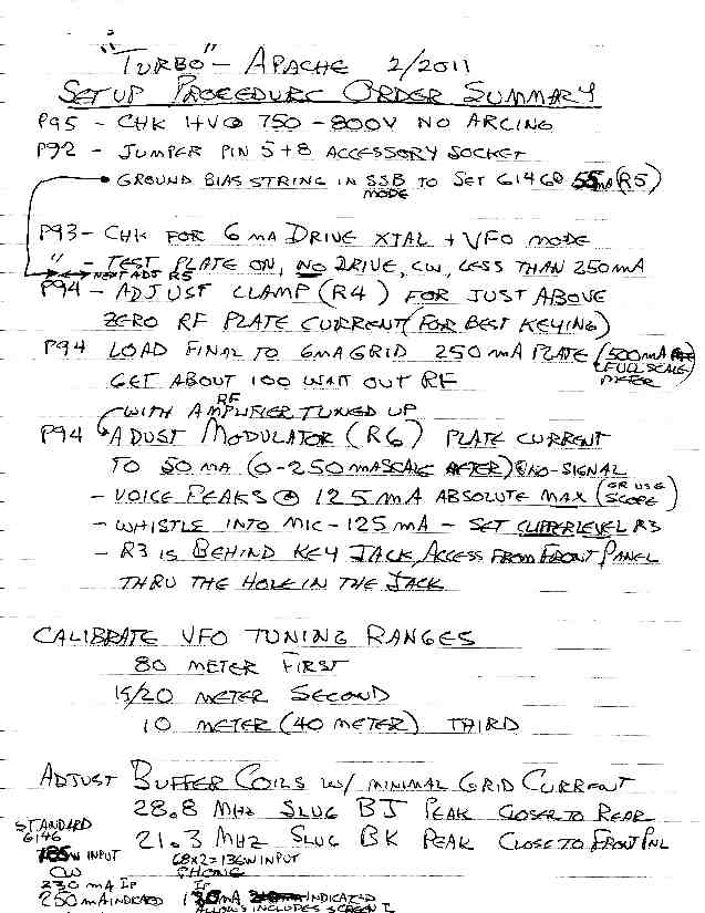
The accessory fan modification came about because Heathkit did not observe the PHONE ratings of the 6146. It ran them in CW ratings on AM. The Warrior amplifier had the same mistake. WARNING: REDUCE THE RF INPUT TO 60 WATTS PER TUBE OR 120 WATTS TOTAL IN AM OPERATION. Measure your current plate voltage (with modern line voltages) and calculate the current necessary to provide the rated power. Allow about 15 to 20 mA for the screens, since you are metering CATHODE current in the Apache. The cathode current is the sum of control grid (negligible), screen grid, and plate current, so it reads higher than the actual plate current. Do not forget to test the accuracy of the shunt resistor in the RF amplifier cathode. I describe the method in the article posted here on the Valiant.
Provide a separate fuse for the LV transformer primary. The main fuse is too large to protect it during receive cycle. Use MOVs to protect from power surges.
The modulator is subject to arcs under the 6CA7 sockets. I suspect this is the problem might manifest itself similar to the problem described at:
http://amfone.net/Amforum/index.php?topic=11953.0;wap2
To prevent damage to the unobtainium modulation transformer, you MUST ELIMINATE ARCING AT THE 6CA7 SOCKET BETWEEN THE SCREEN AND PLATE PINS. A heavy coating of glyptal or equivalent high voltage dope is absolutely necessary on the bottom of the socket. Clean all surfaces very well before applying the fix. Also, make sure there are no carbon arcs on the top of the 6CA7 sockets, or on the tubes themselves. If so, replacement is required. Use only CERAMIC sockets. Once you are done with this, there is a further fix you must do to reduce further instances of arcing. I do this to all new tubes I install in the modulator. Cut a small length of shrink tubing. Shrink it onto the plate and screen pins of both 6CA7s. It should be just long enough that the tube just plugs securely into the socket, but it covers all the exposed length above the socket female connection. THIS JUST BARELY CORRECTS THE PROBLEM. Operate the radio only in a very dry environment. The choice of 6CA7s is a fatal flaw in the design of this rig. I can offer only one fix that works: modify the modulator to use 6146 tubes. They will develop enough power in class AB1 to fully modulate properly operated 6146 finals running at 120 watts RF input. The Apache modulation transformer may not have the right turns ratio to work with 6146s, but from the characteristic curves in the tube handbooks, it looks close enough. Moving the plate up to a plate cap will end the arcing to the screen. This is a major project. The B&W 5100 successfully used a pair of 6146s modulated by a pair of 6146s.
http://www.k3msb.com/bw5100b/bw5100b.html
Given that the modulator had a fatal design flaw of tube choice, I did the best I could with it and sold it. The measures I described above seemed to be working well enough. But I was not happy with the Apache due to the internal VFO and the impossibility of WARC band coverage. I longed for a Viking 2, which solved all these problems, and its admitted screeching audio could be fixed.
There is one audio modification that gets some good marks:
http://k9sth.com/uploads/Not_so_scratchy_apache.pdf
I suspect that a more aggressive approach would be required to suit me. Something more like what I describe to the Valiant elsewhere on my web page. The Apache clipper circuit is a good design. It duplicates the circuit found in the Terman Handbook popular with broadcast engineers of that day. Heathkit implemented it incorrectly by not providing good low frequency response AFTER the clipper. The small capacitor values are OK in the preamp section to tailor frequency response, but not quite so aggressively. The capacitance values needed AFTER the clipper need to be huge. The small driver transformer is pathetic and must be replaced for proper clipper operation or any audio improvement.
You do not have to do any cutting to remove the clipper in the Apache, as is commonly said in the folklore circulating. Just unplug the 6AL5 tube. The clipper is the least of the problems, and can be made to work like Terman intended, if you do it right.
I did a successful modification to add 160 meters. You have to add about 100 microhenries to the driver tuning plate circuit. Radio Shack still sells a suitable RF choke with a ferrite core. You have to add inductance to the RF PA tank coil, about double the inductance in the circuit used on 80 meters. You have to add about 150 to 200 pF of capacitance to the plate tuning capacitance of the RF PA. Switching it all in requires a small reed relay in the exciter circuit, activated by a switch on the top of the RF PA cage. You will have to remove the stock fan and replace it with a more compact unit to accommodate the new switch. The new switch adds the inductance and capacitance noted above to achieve resonance on 160 meters. No changes are needed to the VFO. It already operates on 160 meters and doubles for 80 meter operation. By putting the switch on top of the RF compartment, no holes were drilled in the front panel. Just lift the access lid of the external cabinet and rotate the switch. The band switch on the front panel must be in the 80 meter position.
The Apache was the final AM transmitter in the line.
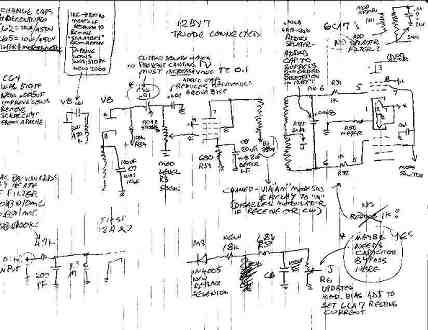
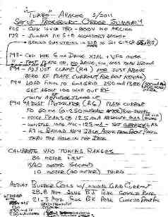
I have had requests for more detail on the Apache that I did up. I always try to accommodate fan mail when possible. Unfortunately, I have lost the picture files when I did the work due to a computer problem. However, I have the paper files in my cabinets and am posting them here. Please pardon any component value ambiguity as I am working from my design notes from some time ago and no longer have the rig to photograph or test against. This should get you in the ballpark if you know what you are doing. CAUTION: LETHAL VOLTAGES! THIS IS AN ADVANCED LEVEL OF WORK TO MODIFY THIS TRANSMITTER. DO NOT PERFORM THIS UNLESS YOU HAVE HAD EXPERIENCE DOING THIS SORT OF THING. AS A MINIMUM, GET A FRIEND TO DOUBLE CHECK IT ALL BEFORE POWERING IT UP, EVEN IF YOU ARE EXPERIENCED. A SECOND SET OF EYES IS NEVER A BAD IDEA.
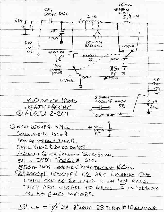
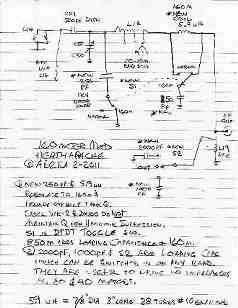
160 METER MODIFICATION
The VFO operates on 160 meters during 80 meter operation, so no modification is required to the VFO.
A three pole two position rotary switch is installed in the hole left by removing the stock accessory cooling fan. This switch should have sufficient insulation, similar in construction to the bandswitch in the Apache. There should be two decks. One deck or wafer should switch the high voltages of the plate tuning padder capacitance. A separate deck should switch the lower voltage padder coil for the tank circuit and auxiliary loading padder capacitor. One separate set of contacts can be used to switch the DC to the reed relay that controls the 70 uH padder coil in the buffer/grid circuit. These connections are as follows:
First, the buffer stages require a 160 meter tuning coil at the high voltage end (not the 5763 end) of the large buffer/grid tuning coil. Radio Shack (in the stores that have the component drawers) a 100 uH ferrite core coil that is compact and works fine for this application. The exact value I came up with is 70 uH. I obtained this by removing sufficient turns from the 100 uH coil to trim it to value. In the spot mode, check the tuning range of the driver tuning. Set it so that the maximum capacitance setting is obtained on the lowest end of the CW band on 160 meters. B PLUS IS ON THE COIL! POWER DOWN WHEN CHANGING THE TURNS ON THE COIL! You can use whatever you have on hand. The switching for this coil can be provided by a small reed relay to short it out. Most of the SPST relays are normally open. If you can find a normally closed (NC) relay, fine. Otherwise get a SPDT relay and use the NC contacts. The ground return for the relay coil can be switched by the switch in the tank circuit described below, but be sure to keep all leads short and put bypass capacitors to prevent coupling from the final tank circuit back into the buffer, which could cause oscillation and instability. Do not forget to put a “catch diode” across the relay coil to prevent spikes when you shut off the coil current.
The DC for the relay can be obtained by rectifying the filament supply. I presume if you are doing a modification of this complexity you can design a power supply to suit your components (the fan and relay coil).
Second, the 160 meter modification RF tank circuit component values. POWER OFF WHEN WORKING ON THIS! LETHAL HIGH VOLTAGE!:
Increase the plate coupling capacitor value by adding another 500pF 5KV doorknob capacitor in parallel with the existing capacitor. This increases power output on 160 meters similar to the Viking Valiant mods described elsewhere. This capacitor is not switched. It is in circuit at all times. It will not harm output on 80 through 10 meters.
Remove the original optional cooling fan on top of the final compartment. Use the hole to mount the new ceramic two deck rotary switch. You can later replace the original fan with a modern DC fan of similar air handling capacity. An appropriate supply must be provided for the reed relay and the new version of the fan. I will leave that to you, since you have freedom to choose coil voltage and fan voltage. This new fan will actually work better than the original since it can be mounted directly over the 6146s, rather than just attempting to cool the compartment. You can provide for demounting the fan for chassis removal if necessary, which is a problem with the stock fan also.
You will have to rearrange some of the components in the final compartment to accommodate a new ceramic rotary switch to switch to the 160 meter mode. The Apache bandswitch MUST be in the 80 meter position to obtain 160 meter operation. Never invoke 160 meter mode in any other position. This modification makes no front panel holes and is reversible. The top door on the cabinet provides access to the switch. The following describes how to wire the switch.
Add a 250 or 300 pF 5 KV doorknob capacitor of sufficient voltage and current rating to the 350 pF plate tuning capacitor. The bottom end of the capacitor goes to a two position ceramic switch similar in construction to the bandswitch. The other SPST contact goes to ground. This capacitor provides correct circuit Q for harmonic suppression. The DX100 and Johnson Viking 2 do not use this capacitor. You can also choose not to include this piece if you want to duplicate the design of those rigs. The coil described next must be increased to obtain resonance if you go that way. Use the DX100 coil or Viking 2 coil in that case. That coil is too big in value for this design, but if you consult pictures of those rigs, you may get an idea of its construction.
Add about 10 uH coil in series with the final tank coil at the antenna end. One of my prints shows 5.9 uH as a final value when using a 250 pF doorknob as a plate tuning padder. Use a grid dip oscillator to test for resonance. Or use a MFJ259 and a 2K resistor in the plate circuit (POWER OFF!!!!) and look back in to the antenna connector for 50 ohms non reactive as you check values. See the MFJ application notes for how to do this or consult the W8JI website. I will leave the diameter and length to you, since you have to chose from available forms or coil stock on hand. This value works with the capacitor described above. My notes show 7/8 inch diameter and 3 inches long 28 turns of #10 enameled wire. This should get you in the ballpark. The coil is in this end of the tank coil to reduce voltage requirements of the switch and coil form insulation. I will describe the switching arrangement with the auxiliary loading capacitor, which comes next.
Add a 820 pF minimum to 1000 pF fixed mica capacitor to ground. The floating end goes to the switch position which is closed for 160 meters.
The second wafer of the ceramic rotary two position switch is wired as follows, in DPDT fashion:
- The wiper goes to the ANTENNA connector on the Apache.
- The 160 meter position goes to the auxiliary loading capacitor.
- The 80 meter position goes to the new 10 uH coil to short it out on all bands except 160 meters.
The third wafer of the rotary switch sends DC to the reed relay that switches in the 70 uH buffer/grid coil for 160 meters. That relay is deactivated on all other bands, and shorts the 70 uH added coil out.
I WILL PROVIDE A DRAWN SCHEMATIC OF ALL THIS LATER.
NOTE ON 160 METER LOADING and tuning procedures for any band and any rig:
Set this up for a 50 Ohm dummy load during initial test to optimize the coil inductance to make sure the plate tuning is not out of range on the CW end of the band. Try to keep the plate tuning capacitor as closed as possible while still tuning the whole band. IF YOU FIND YOU CANNOT GET A GOOD DIP RUNNING INTO YOUR ANTENNA, you can add more capacitance to get a minimum plate current that is in spec. You may need to add more capacitance with an external 1000 pF or 2000 pF. I use a small aluminum chassis box with coax connectors on either end, and a switch to select from the added loading capacitors. This is a handy item to have on hand for any rig when you are matching low impedance antennas like a shortened vertical or Marconi on 160 or 80 meters. Provide a switch position for “OUT” or no capacitance added, and the signal passed through direct to the output coax connector. Usually, I keep short leads to the loading box from the transmitter. This may also work if you have a dedicated 160 meter antenna on an antenna switch if you just put a fixed loading capacitor permanently in line for the 160 meter antenna only.
NEVER SWITCH ANY BANDSWITCH OR AUXILIARY COUPLING
CAPACITANCE DURING TRANSMIT. TUNE UP IN CW MODE ONLY AND LET UP ON THE KEY BEFORE YOU
ADJUST AUX COUPLING SWITCH! You may make fine adjustments to variable capacitors only in AM mode
to touch it up.
To review this:
- FOR 80 THROUGH 10 METER OPERATION, THE NEW SWITCH IS SET TO NORMAL.
- FOR 160 METERS, BANDSWITCH IS SET TO 80 METERS ONLY, AND THE NEW SWITCH IS SET TO 160.
Operation of the rig with the band switch in any other position and the 160 meters set to IN will not work, and could result in damage. This is true of the Viking 2, which has a similar switching arrangement.
OTHER IMPORTANT CHANGES CULLED FROM MY FILES:
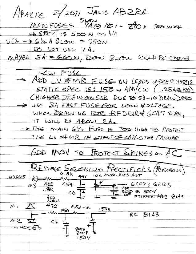
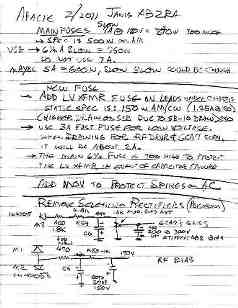
Add a fuse to the low voltage transformer primary. I found a 3 amp fast fuse was OK if you did not have a SB10 hooked up to it.
Try a 6 amp slow fuse for the main fuse. It will hold and provide more protection than the stock 7 amp slow blow fuse which is not needed if there is no SB10. This is better protection than the original fuses, which assumed you would have an SB10 drawing the extra current.
Add MOVs across transformer primaries to prevent AC line spikes from damaging.
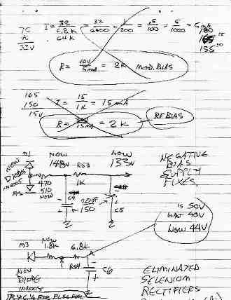
It is important to replace the stock selenium rectifiers, even if they are working. The gas emitted by a failing selenium rectifier is POISONOUS! Use any common silicon diode to fix the problem, and completely disconnect or remove the original selenium diode. You may have to readjust bias resistor values, since the new diodes have lower forward drop. I found in my rig that adding 1.8 K in series to R54 6.8 K was OK in the M3 diode circuit. Add a new 470 ohm in series with the common anodes of M1 and M2 with an extra 20 uF filter capacitor and R53 to its stock 20 uF filter capacitor for the RF bias circuit. This results in 133 volts. These values seemed to return the voltages to those called for in the troubleshooting section of the manual. Check these bias voltages against your manual before attempting to transmit with the Apache. Do these mods one step at a time and test them. That way, if there are any problems, you will know where to look. OBSERVE CAPACITOR POLARITY! It is easy to get in the habit of hooking the minus lead of a capacitor to ground; remember this is a NEGATIVE bias supply!
If you are running a stock Apache, put a 0.0068 uF capacitance across the primary of the audio driver transformer. This prevents second harmonic energy caused by distortion of the 12BY7 driver stage. This will prevent splatter when using the original design. This transformer has a nasty peak at 8 KC when using a 0.01 uF capacitor to load it. This is the best you can do with the original audio driver transformer and a single ended driver.
NO MORE SCRATCHY APACHE, AND KEEP THE CLIPPER!
I got good reports for audio with this setup. The following describes a minimalist modification that does not go to a push pull driver or change the original driver transformer, although that would be a good choice, especially if you went to 6146 modulator tubes. This is not wide body hi-fi AM, but it is good communications grade audio that does not splatter.
Before you go hacking up the Apache, give this a try. To make the original clipper circuit work right, you must keep the low frequency response after the clipper as good as possible on the low end. Any further contouring then is done in the preamp, but I suggest you do not go wild on the bass since clipping makes any boominess worse. Try this first. You must:
- Increase the original 12BY7 cathode condenser from 2 uF to 20 or even 100 uF or more.
- Check the value of the 680 ohm cathode resistor. It may reduce in value and cause failure of the driver transformer.
While you are at it, you can change the transformer wiring so that its plate supply is provided by the 6CA7 screens, which are driven from the low voltage supply and switched by the T/R relay and the mode switch. This will afford some protection for the driver transformer should the 12BY7 develop a heater to cathode short. At least in unattended warmup mode, no plate voltage is on the 12BY7. When transmitting, if you lose modulation and are alert, you may power down and investigate before damage occurs. Another fix is to install a 0.1 amp fuse in series with the plate supply to the 12BY7 audio driver to protect the transformer.
Make the cathode bypass capacitor from V8 pin 8 as big as possible.
Add a 200 uF @ 300 V capacitor to the bias pot wiper that feeds the 6CA7s to stiffen up the bias when you run them into AB2 mode. OBSERVE CAPACITOR POLARITY! This is a negative bias supply!
Finally, to flatten out the mid range, change only one capacitor, the 510 pF that connects to V8 pin 2. Change it to 2200 pF. Try this before you change the other coupling capacitor. This will be fine, if you are using a D104.
DO NOT REMOVE THE SPLATTER FILTER CAPACITORS FROM THE OUTPUT OF THE MODULATION TRANSFORMER. This unwise move will increase bandwidth and possibly allow damage to the modulation transformer from high frequency transients. Transients may occur if there is arcing under the 6CA7s or sockets from the plate to screen as previously discussed.
Remember to use the PHONE ratings for the 6146s. The manual says to use 250 mA RF plate current for everything. That is 90 watts per tube. I use 200 mA. If you solid state the 5R4s, the plate voltage may rise and you will have to cut it back to 180 mA RF plate current in PHONE. I recommend that you keep the same plate voltage.
Solid stating the 5R4s may increase arcing under the 6CA7s. If you provide a series resistor in the solid state replacement that simulates the dynamic resistance of the 5R4 to obtain the original plate voltage, you will avoid undue HV transformer heating and all these other associated problems. Consult the Valiant modification article on this page where I describe how to do it for the 5V4 and follow the same idea for the 5R4.
Do not increase the idling current of the 6CA7s from what is stated in the manual in the mistaken notion that you will get more linearity. These work very hard in the Apache. If you do not think so, run it into a dummy load and whistle into the mike briefly while watching the 6CA7s in a dark room. Makes you think.
I enjoyed my time with the Apache. It was great fun to operate 160 AM and casually mention I was running an Apache, and wait to see if they would tell me that is impossible.
If operated conservatively, this classic rig will deliver good communications audio, and last a long time. I eventually wanted a Viking 2 due to its coverage of the WARC bands and it is easier to work on. The linkages on the front panel controls are tricky. The audio stages are crammed in a little box.
NOTE - These hand drawn schematics and calculations are retrieved from my files in response to fan mail for the webpage. While they are not complete, a competent technician can recreate everything from these design notes. The audio mods are straightforward and require no further explanation than the discussion on this webpage. The power supply mods include the calculations so you can adjust it for your available components. NOTE: Very important: Always replace selenium rectifiers since they emit poisonous gas when they fail, for safety reasons.
The 160 meter mod does not change the operation on the normal 80 through 10 meter bands. The internal 160 IN - OUT switch is set to OUT for that mode. For operation on 160 meters, set the original front panel band switch to 80 meters, then set the new internal band switch to 160 meters. NEVER operate the rig with the 160 meter switch set to IN and the front panel switch on any other than 80 meters. This is similar to the Viking 2 operation. The component designators, like C13, refer to original Heathkit parts. They are given as a guide to installation of the new components. The 160 meter mod schematic is a simplified functional schematic which does not show all components, but only the ones you need to identify where the new parts should be connected.
To preserve the original final compartment top cover to undo the mod at a later time, buy some new expanded metal (sheet metal with holes in it) at Lowes. Mount the new fan and 160 meter IN - OUT switch on that new metal. The 6146 PLATE tank capacitor, coil, and other Plate circuit parts all fit inside the final compartment for TVI protection. The 70 uH coil and switching relay added to the driver tank coil in the 6146 GRID circuit mount near the associated components.
|