|
The DX60 was one of Heathkit's better offerings. I have worked on DX-60s for friends, and was impressed. This rig has gained my respect for sure.
Thanks to a friend, I now have one of my own. It was an entry level rig, but it used parallel tuned exciter circuits, grid block keying, neutralization, and good performance
for a very modest price. Some Heathkit and Hallicrafters rigs used a Pi network circuit to couple drive to the final amplifier grid.
This is a low pass filter. It made neutralization a challenge, and also allowed lower frequencies to pass through to the final amp. The antenna coupling circuit is
also a low pass filter Pi network. The combination allowed an unanticipated "subharmonic" output on multiple bands, often outside the Novice spectrum.
See this for more details:
https://wireless-girl.com/Projects/AMTransmitters/Subharmonics.html
It even offered a modulator that with minimum work sounds really decent. It makes a good exciter for a big amplifier,
and does well on its own in good conditions. There is even a net dedicated to its memory, the DX60 net.
https://dx-60.net/index.cfm;jsessionid=02CD9A6A747C835E62DF06B5A4472F88.cfusion?key=main&CFID=113019204&CFTOKEN=d6751a99202fef22-EEB97A3F-B3D2-46F8-755FAFBE673A084B
It works very well for an economy transmitter.
There are lots of resources on the web for this rig, and I recommend that you get one of these radios and play with it. The closest competitor was the Eico 720, which used cathode keying,
was not neutralized, and employed a pi network interstage coupling circuit to the final. The Eico did not have a screen modulator, but it did offer the Eico 730 plate modulator.
The Eico 720 - 730 AM transmitter was an excellent performer, and I would prefer it to the Johnson Ranger any day; the Eico system was simple and easy to work on.
The biggest problem it has is the rotary function switch, a flaw common to the era which showed up in the DX-35, DX-40, Johnson Ranger and Challenger, Eico 720 and many others.
The rotary function switch contacts fail due to frequent operation and contacts not being rated for the current during power up and charging the large filter capacitors.
Terry N6TLU has a push to talk relay kit that fixes some of these problems by reducing the number of times the function switch is rotated;
the K1 addresses the basic problems, and the K2 kit has two extra sets of contacts for amplifier keying and receiver muting. Even though the DX-60 has humble roots
as a kit project, this is not a Chevy, its a Cadillac design, head and shoulders above the competition.
The only Novice class rig better than the DX-60 is the Drake 2 NT, and fewer of these are available for restoration, because of the original high price.
With the matching 2C receiver, it made a high performance full break in CW station that even a General Class operator would be happy to have. After its brief life
the Drake gear went the way of all Novice rigs, as the No Code Revolution took over, and the Technician class became the entry point for most hams.
If you are uncomfortable working on your DX-60, try this repair service: http://www.rtoham.com/product/repairs-dx-60/
WHAT THE DX-60 MANUAL DIDN'T TELL YOU: Repair of the Heathkit DX-60 is simple and straightforward. A complete manual or at least a schematic is a must have item for any competent restoration. Don't fly
by the seat of your pants without a map to guide you. Test the tubes to eliminate a lot of head scratching later.
The next item is a replacement from Hayseed Hamfest for the main can style filter capacitor.
The fit is flawless, just like original. The can is a beautiful chrome finish that will look great for even the most demanding collectors.
The full kit comes with the other electrolytic capacitors as well as the audio and modulator capacitors.
Some may want different capacitor values for the audio
section, due to modifications. The stock audio is flat from 200 Hz to over 6 KHz at the 3 dB points, with very gentle roll off. Keep that in mind when working near the band edges; I would not recommend
using a DX-60 above 7290 KHz, especially if you are driving an amplifier. I have found that a good D-104 mike is all the audio processing
I will ever need on many AM rigs, and the DX-60 is no exception. In stock form, the DX-60 makes 100% modulation. I recommend DX-40 owners simply change the circuitry
to match the DX-60B for best performance. Some kind of power reduction is necessary, if you need to use the DX-60 with an amplifier.
Do NOT get carried away with a lot of modifications or chassis polishing until you first get the rig running in stock mode.
The biggest single problem that manifests itself is a failed function switch. The meter switch also may need cleaning or replacement.
Use only a cleaner without any greasy lubricant or conductive elements which can be absorbed into the ceramic wafers. This may later cause arcing.
If the function switch does not respond to cleaning after a couple tries, it isn't the end of the world. See the work arounds later in this article.
I always bring the rig up on a Variac with a voltmeter and ammeter before I do any work at all, other than tube testing and switch cleaning.
A 60 watt incandescent light bulb in series with the AC feed is a good idea at first.
That way you don't invest a lot of work and parts in a radio with a dead transformer.
You can learn to be a systematic professional restorer instead of a mindless parts swapper, with a little experience and minimal test equipment.
Many people dive into "shotgun" replacement of parts before even an initial test, and introduce new wiring errors which are hard to troubleshoot.
When you do get the radio to a point that it makes sense to do a full rebuild, change one or two components at a time, and check that the radio
still works. A step wise approach will reward you with a working radio; it will also spare you the frustrating retracing of all the connections against the schematic
to find out where the project went wrong.
Keep in mind this IS a kit, and
the original builder may have made some mistakes.
Or someone may have gotten in there with a bunch of undocumented half baked mods. It is so disappointing when you buy gear from a radio butcher. You may have to
use the schematic and rip all this junk out before you even begin to do a restoration.
This is not intended to disparage the competent modifications which are documented on the internet. But there are goofs in even the good ones. One such mod shows a 50 ohm
resistor to ground from the cathode of the 6DE7 which drives the 6146 screen. The correct value is 50 K ohms. Bad stuff happens with 50 ohms, which the novice
restorer will probably not figure out before damaging a lot of stuff. Once more for emphasis, get it running stock before experimenting with modifications.
You may like it just fine the way it is, and it does not destroy the value of the gear to keep it stock.
Before you begin any of this, you should have a set of good tubes installed, cleaned the switches, and replaced the filter capacitors with quality new components.
I use either Hayseed Hamfest caps or premium quality capacitors I have obtained from Mouser rated at 105 degrees Centigrade. Thse will take the heat generated
in tube gear and be more reliable. If you have a DX-60A, it is notorious for hum problems.
Change the circuit and install capacitors in the High Voltage and Low Voltage supplies to match the DX-60B. The original DX-60 was OK.
Hayseed Hamfest has a special kit for the DX-60A to convert it to the proper DX-60B circuitry. It even comes with the terminal strip and other
components. Their stuff is exact fit, super quality, and easy to follow instructions. Save your time and and hassle, do it right, and get
a cosmetically perfect result. The right kit is lower on the page.
https://hayseedhamfest.com/products/dx-60a-re-cap-kit
TUNING OSCILLATOR COIL L1 Be sure to test R5 for overheating and change in value. It is OK to use a modern resistor to replace this component, because it has no RF on it due to the
bypass capacitor. The manual tells you to adjust this coil for maximum grid current at a certain frequency. I wanted to use my DX-60 on 10 meter AM,
so I tuned it for 29.1 MHz peak. Some crystals may not start quickly, which is important on CW (less important on AM as long as they do start).
If you have this problem, tune the coil for less inductance (to a higher frequency) while listening to your CW signal on a receiver.
It will be apparent when the signal sounds OK, and you have the sweet spot. Normally, if you peak the coil on a phone frequency, the CW
will be OK on keying.
V1 AND V2 GRID CONNECTIONS: Terry, N6TLU reports contact problems with these tubes resulting in erratic keying. He recommends installing a jumper
on the tube socket between pins 2 and 9. Both of these tube pins are the same tube element, the control grid. If you connect BOTH, you have a better chance
of making connection on a dirty tube pin. I like to use contact cleaner on the tube sockeet (non greasy, solvent only) and clean the tube pins with
Skotchbrite (green scrubber like you use to do the dishes, but without soap). Don't use steel wool or the conductive particles will fall in the
equipment and short things out.
IMPROPER LOAD IMPEDANCE TO MICROPHONE: The D-104 likes a high impedance load. Remove R16 1 Meg from the mike jack. Now the load seen is
R18 2.2 Meg. Better low frequency response will result. See discussion later in this article.
REPLACE THE RCA OUTPUT CONNECTOR WITH A SO-239 CONNECTOR: Disconnect the wire going through the final compartment to the loading capacitor.
Remove the mounting nuts on the bottom of the chassis holding the low pass filter. Fix the output connector. Reinstall the low pass filter assembly.
FUNCTION SWITCH PROBLEMS, AC POWER CONTACTS If your function switch AC contacts have failed, just install a jumper wire between contacts 11 and 12 and use an external switch to control the rig for now.
You could use an outlet strip to power up the whole station, and still enjoy your DX-60.
There is a way to prevent this failure of the rotary function switch AC contacts.
I recommend a thermistor inrush current protector in series with the AC line.
This reduces the stress on the AC contacts on the rotary switch.
This is caused by charging the huge capacitors and the filament inrush current.
Here is the part: Mouser P/N 527-CL-90A
Its rated for 2 amps, which is enough.
I also installed a 3 amp fast fuse and fuse holder. The glass circuit breaker is crap.
A 3A fuse is adequate if you use the thermistor recommended above.
I remove the glass circuit breaker and wire the fuse to the terminals freed up by the removal.
I mount the thermistor on the rear terminal of the fuse, in series, to keep it away from wiring. It can get warm.
Peaks of more than 5 A are seen without it, explaining why the fuse would blow on power up; now this saves the switch from surge current in excess of 5 A.
Easy-peazy, no complicated relays or time delay circuits.
FUNCTION SWITCH PROBLEMS, HIGH VOLTAGE CONTACTS There are contacts that switch the HV and LV supplies off in STANDBY mode. These contacts are in series with the
secondary winding. There is a huge inrush current
to charge the large electrolytics in the DC supplies. Eventually the contacts fail if this problem is not addressed. I have seen people salvaging stationary contacts from
another generic switch, and mounting them with a #2 screw and nut. If the rotating part of the switch has a "bite" out of it, you probably are not going to be able to correct
this failure in a way that resembles stock performance. A junk DX-60 or DX-40 is the only source. You could invent a relay system using a generic switch, but even these are getting
scarce in the ceramic styles that are rated for the DX-60.
Here are a couple of ideas to repair a bad DX-60 rotary function switch.
http://ve6kq.com/dx60bfunctionswitch.pdf
Two radical approaches are possible. One involves replacing all the rotary switch functions with toggle switches. This is 100% reliable and will last forever. The panel of
the DX-40 lends itself well to this solution; the DX-60 has less space.
This of course means drilling a lot of holes in the front panel. If your DX-60 is ugly anyway, maybe this works for you.
The other approach is to simply short out the bad contacts (pins 4 & 5) so that the HV and LV DC power is always on. This is not as nuts as it seems. And it doesn't
butcher up the rig with front panel holes.
If you use the N6TLU D-Labs Push to Talk
relay K1 kit as he suggests in his instructions, the transmitter works fine without switching the HV and LV. I tried it. But don't go sticking your fingers in the rig with the
power on. You wouldn't do that anyway, would you?
If you get the D-Labs K2 kit, there is a second relay with two more sets of contacts. These contacts are rated
250 VAC and 5 Amps. I don't know if the voltage rating is quite enough, but you may be able to use it to fix this problem. If you do this, use one relay for the VFO and antenna
relay switching function. Use the second relay ONLY for the HV power supply switching function. That way, if it fails shorted or arcs, it may not affect the
other circuits. This is a risk you alone will have to decide to take; I haven't tried it, and it is outside the ratings of the components, and
I recommend against this practice.
Maybe you can use the K2 kit to drive a bigger relay with sufficient ratings.
Assuming you have a good set of HV contacts on your DX-60 function switch, install a terminal strip, and mount a 5K 5 Watt wire wound resistor. Wire the resitor
in parallel with the HV switch contacts. This keeps the HV and LV power supplies in a limited "keep alive" mode that keeps the capacitor bank charged. There is very
little inrush current that shows on my Variac ammeter this way. It saves the contacts.
This idea comes from Timtron WA1HLR, and it worked for me. Its a minimal impact no front panel holes or drilling and blasting modification. I like it, and that's the
way my DX-60B is now.
Another design fix is to isolate the HV contacts on the rotary switch and use them to switch the coil of a heavy duty relay. Connect the HV switching wires from the
transformer secondary to the relay contacts. No stress on the rotary switch any more.
So there are a number of ideas for recovering from a rotary switch failure, or preventing it from happening to you. This is the ONLY design flaw in this
otherwise excellent transmitter. I hope you found one that works for your DX-60.
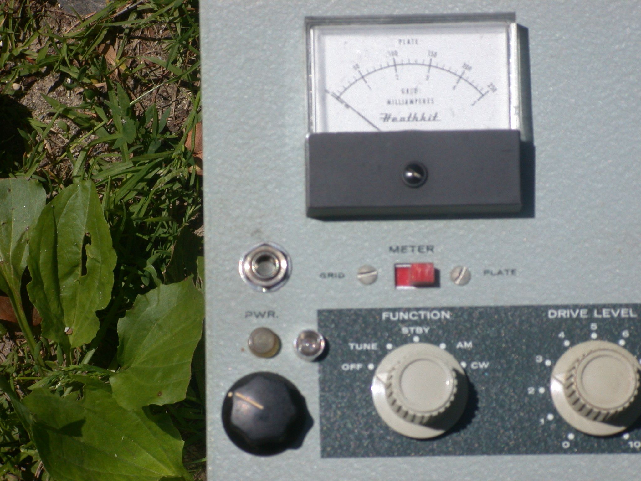
METER PROBLEMS, PROTECTING THE METER One of the very first things I do on these vintage projects is protect the meter.
I install two 1N4007 or equal rectifier diodes in parallel with the meter. One diode points right, one diode points left.
Either polarity of overload will be limited to 0.7 V DC and may save the meter.
The 6146 8.2 ohm R13 cathode resistor can be replaced cheaply with a 2 Watt or even 5 watt resistor. Use a 5% or better yet 2% resistor.
This resistor calibrates the plate current reading.
If the tube shorts or malfunctions, it can burn out the lower wattage stock resistors.
A heavier resistor will protect the meter. IF the resistor burns out, ALL of the 200 mA final current goes through a 1 mA meter.
It gets very unhappy, bent needle, or open coil. Take out some insurance.
The slide switches used for meters on Heathkit gear are often problematic, because the original silver plating is rubbed off by frequent operation.
If you clean the switch and its still flaky, replace it with a new switch. You may decide that a miniature toggle switch is more reliable.
If you use that method, get a switch with a center OFF position. This saves meter wear in CW, bouncing between full power and no power.
There is a 2K resistor R14 in series with the meter. Check its value, it may have changed. This resistor affects both grid and plate current readings.
R11 and R12 are 820 ohms carbon resistors and may have changed value. If they measure 410 ohms because of parallel connections, with the meter switch in PLATE
position, they are OK if within +/- 5%. This is the resistor that calibrates the grid current reading.
If you are getting low power or strange operation, the meter may not be reading correctly. For instance, if the meter indicates plate current
that is higher than actual plate current, you may tune up to what you think is correct, and get much lower power output.
In my restorations, I calibrate meter readings to 1% with parallel or series resistors. I use a variable 12V power supply and a 1K (plate) or 10K (grid) series resistor and
a digital milliammeter. The AC power must be disconnected from the transmitter for these tests. For the grid current, attach the test source and meter across the sense resistor.
For grid current, use R11 & R12 for connection. For plate current, use R13 commection. Trim the resistors in the transmitter with parallel or series resistors so the DX-60 meter matches the
digital meter.
For a complete understanding of this technique, see:
https://www.w8ji.com/metering_amplifier.htm
NEUTRALIZING THE DX-60 Those of us who grew up around vacuum tube equipment are comfortable with neutralizing an RF amplifier. For those
of you who entered amateur radio using solid state gear, it may appear daunting. Its not as tough as you think it is. Once you adjust a DX-60, you will confidently
neutralize any rig. The objective of this tuning procedure is to balance the plate to grid capacitance with an external capacitance, to prevent instabilty
of the amplifier, which can turn into an oscillator with enough positive feedback. In this case, the adjustment capacitor is a stiff wire placed near the 6146 plate.
When neutralizing any transmitter, BEWARE OF HIGH VOLTAGE and follow all relevant safety procedures. Never touch anything inside a transmitter with the power on. Discharge
all filter capacitors or wait til they discharge. If your DX-60 will not properly neutralize, the likely cause is a bad resistor in the Parasitic Choke attached
to the 6146 plate cap. See the section here below on the Parasitic Choke.
The Heathkit DX-60 manual gives good instructions, and I will not repeat them here. The intitial setting stated in the manual of 1/4" away from the 6146 should be a good starting point.
A perfectly neutralized amplifier will show a slight peak or no movement of grid current when the plate tuning is swung through resonance. Plate current dip should coincide
exactly with a small grid curent peak or no movement at all. If the grid current is jumpy, the neutralizing is not working right. The hallmark of a properly designed
transmitter is a neutralizing circuit. The Heahkit DX-60 does not disappoint us on this item. Many competitors did not include this important feature.
If the 10 meter output is lower than other bands by a significant amount, fix the Parasitic Choke resistor before proceeding with neutralization.
For a full understanding of the technique, see:
https://www.w8ji.com/neutralizing__amplifier.htm#Grid_Driven
PARASITIC CHOKE TESTING AND REPLACEMENT IN THE DX-60 It is a good idea to test the resistor inside the coil of a parasitic choke of an old amplifier.
The purpose of the resistor is to damp out the Q of the surrounding coil, so it is not sharply resonant. The purpose of the coil is to reduce the inherent resonant
frequency of the tube internal structure to a lower frequency, where the tube is stable. The 6146 is rated for full output power at 60 MHz and reduced power at 150 MHz; it has
significant gain at frequencies higher than that. It will be very well behaved in circuits below 30 MHz, if neutralized. The term that describes this is
unconditionally stable - at any settings of Plate, Loading, and Grid tuning, with any load. If the plate or grid current is jumpy, you have a stability problem
caused either by improper neutralization or a malfunctioning Parastic Choke. This can result in circuit breaker trips, blown fuses, or failed cathode resistor
R13 with subsequent meter failure. Bigger amplifiers are much more spectacular fireworks shows.
For a full understanding of the operation of a Parasitic Choke, see:
https://www.w8ji.com/what_does_parasitic_suppressor_do.htm
To properly test the Parasitic Choke assembly, remove it from the transmitter. Do not cut any wires. With heat from a soldering iron applied,
carefully unwrap one end of the coil from the resistor. Once the resistor is isolated, test it with a digital meter. It should read +/- 10% from 47 ohms.
If its OK, reassemble the choke and reinstall it. Don't just change it to change it. Modern resistors do not have the necessary characteritics to
operate properly in this circuit. They are inherently inductive. Old style carbon composition resistors are BETTER in RF circuits.
Unfortunately, this is not the kind of stuff they teach in schools any more. A spice model based on DC performance will NOT work for RF circuits.
If the Parasitic Choke resistor is out of spec, it probably was stressed by bad neutralization or excessive high power operation on 10 meters, possibly by a
CB operator pushing too much power through the equipment or a bad antenna. Don't worry, there ARE still good resistors available.
Use ONLY OX or OY series resistors. The correct resistor for the DX-60 is a 1 watt Mouser P/N 588-OX-47-E. You could try a 2 watt Mouser P/N 588-OY-47-E, but it may not fit the original
coil. DO NOT BEND THE COIL to accommodate the wrong resistor or it will affect the resonant frequency.
If you experience the following symptoms on your DX-60, check the Parasitic Choke resistor.
- Jumpy grid and plate meter readings on 10 meters and maybe 15 or 20 meters
- Low output on 10 meters, maybe only 30 watts, with the antenna loading capacitor near maximum capacitance for max output
- Destroyed 6146, red plate during operation; a 6146 should NEVER show color
- Grid meter deflects negative off scale after red plate; indicates gas or grid malfunction in tube due to stress
- Blown circuit breaker or fuse
- Burned out R13 8.2 ohms 6146 cathode resistor
- Squirrely results during neutralization
- Possible overheating of R5 oscillator plate resistor
RESISTOR AND CAPACITOR TESTING AND REPLACEMENT IN THE DX-60
I am not a big fan of replacing stuff just to change it. Certain resistors like the higher values such as 22 Meg will change value.
These may need replacement, but if it ain't broke, don't "fix" it. Check the 1 watt and 2 watt resistors.
If R28 10K 2 watt is high, RF output may be low on CW.
If R25 1 meg is high, phone output may be low.
Modern resistors are OK for the power supply and the audio circuits. They will not work for RF circuits, because they are inherently inductive
and will detune or mess up the RF performance. The only resistors suitable for this work are OX or OY series resistors. See the section on Parasitic
Chokes for details. These resistors or original NOS carbon composition resistors are the only types you should use in RF circuits. Some understanding of
the theory of the circuitry should guide your selection of resistors. For example, R13 is bypassed to ground by a ceramic large value capacitor; you can use a standard
modern resistor (which has better accuracy) to replace this. Even a wirewound 5 watt resistor will work. R5 is bypassed by a ceramic capacitor and
its OK to use a modern resistor. R1 is NOT bypassed on the HOT end (the grid) and you cannot use a modern resistor, only a non inductive resistor.
Definitely do not use a modern resistor in the Parasitic Choke, unless it is type OX or OY.
Same thing with capacitors. Wax or electrolytic capacitors should be replaced.
Ceramic or mica capacitors don't need to be replace "just because".
The one exception to this is C21. It may fail if someone tries to operate the radio without a load. This will be evident if the rig works on all bands except 80 meters.
Use ONLY ceramic capacitors to replace ceramic capacitors. Same thing with mica capacitors. Wrap and fill film polystyrene or similar caps are OK for audio, but they
will not work in RF circuits.
The Heathkit instruction manual has excellent troubleshooting tips. Be sure to download a complete manual, not just the schematic. In general, the manual
gives good information on all variants from the original, the A version, and the final B version.
If the 6146 draws excessive plate current even with the cw key circuit open, unplug the 6146 and do troubleshooting of the grid bias circuit.
This prevents damage to the 6146 tube. None of the tubes in this rig should ever show red color on the plates, even operating at full rated power.
The negative bias supply is essential for all tubes in this rig. All RF tube cathodes are basically connected to ground and will draw excessive current
if no negative bias is present.
Excessive current may happen if there is a heater to cathode short in the 6DE7. Screen voltage at the 6146 will be low as another symptom, so AM RF output and plate current will also be very low. CW output and 6146 plate current will be nearly normal. To troubleshoot this, power off and unplug the AC cord, unplug the 6DE7 tube, and measure resistance from V4 pin 9 to ground. It should be open. Sometimes tubes don't show a heater to cathode short unless they have the filament lit; to test for this, swap a new tube for V4.
Yeah, people love to have the "matching" VFO or whatever. Sometimes the "matching" gear isn't what its hyped to be.
The HG-10 can be a very good VFO if built properly. The gear train for tuning is a bit touchy to assemble, and the parts
are unobtainium. The tube is hard to find. And you may need to select from a group to find a stable tube. The grid block keying
would have been nice if the radio was full break in. But with the rotary switch to change function, it isn't break in.
The closest you will come is to install a good PTT system, and use a foot switch. One other thing about the HG-10.
I have had a friend with a problem that the HG-10 runs all the time (at a lower level of output). The quirky
neon bulb circuit depends on the characteristics of the neon bulb. As they age, they can cause this problem.
We finally gave up and wired it for cathode keying and used spare contacts on the D-Labs PTT relay kit to key it.
He is primarily an AM operator, so any small benefit of grid block keying for CW is irrelevant for him.
I suppose we could have gone through my junk box til we found a neon bulb that worked.
I have heard that installation of a 1 Meg resistor to ground helps the neon bulb stay lit better.
I have no details on this, and you may want to experiment with yours to make it work.
The DX-60 will work just fine with ANY VFO. The Heathkit VF-1 is plentiful and cheaper than the HG-10.
With some work, its stable enough to have fun. The 6AU6 tube is easier to find, and you can swap til you get
a good one. There is a mod that substitutes another type that claims to be more stable.
There are other mods out there for the VF-1 on the web.
One even allows choice between cathode keying and grid block keying. Its a pretty good mod,
and you can switch modes to move the VFO around between rigs when you want to. I use my VF-1 with my DX-60,
as a cathode keyed VFO, because I could not see any advantage to making the converson. With the K2
D-Labs kit, its easy to use the spare contacts for cathode keying. Maybe I will find an HG-10 at
the right price, but I'm happy for now with a VF-1.
I have also tried a Hallicrafters HA-5 in cathode keyed mode. It is an extremely stable
heterodyne VFO. The basic oscillator runs at 5 MHz on all bands, and uses crystals
to change bands. Rock solid signal, and no chirp at all.
Its expensive, but worth it. I have not tried the HA-5 in grid block keying
mode to see if it works with the DX-60. The HA-5 can be wired for either style of keying.
You can get real fancy with a fully synthesized modern VFO for maximum stability
and frequency accuracy. A great product, and probably not much more than you would
pay for a vintage tube VFO.
https://www.wa1ffl.com/
On any of these VFOs, I use the PTT relay contacts to key the VFO. The
effect of this is that when the PTT is activated, the VFO is ON and generating a signal.
This completely eliminates any chirp, because the VFO runs whether the DX-60 is keyed or not.
When the PTT is released, the VFO stops, and the receiver mute is switched to receive.
This is a much easier approach than hassling with full break in.
Full break in would have required a T/R switch such as the E. F. Johnson unit.
WARNING: Do not use a solid state receiver with the E. F. Johnson T/R switch.
Initial transients during transition to transmit will blow out a solid state receiver.
Any T/R relay using carrier detection to activate should be viewed with suspicion,
due to the activation time of the internal relays and circuitry.
Operation with a D-Labs PTT relay kit is so much better than when I was a Johnny Novice.
I had to operate the receiver mute, the antenna changeover knife switch and the plate switch
on the transmitter, in the exactly correct order. Big improvement on CW, absolutely
essential on AM.
The keying with a VFO is very sharp. With crystals, it seems to be much softer. With the ARRL Clean Signal Initiative,
it would be a good idea to pay attention to key clicks. The DX-60 is not known for a clicky signal, but on the scope, it has that potential.
I don't have an HG-10 VFO, so it may look better on that setup. One factor that may present itself is aging in the neon keying bulb in the HG-10 can cause
a constant carrier. I was working on this for a friend, but he was in a hurry, so I was not able to explore it further.
We compromised by cathode keying the VFO ALWAYS ON when the DX-60 was placed in transmit. This results in minimum chirp, but it means break in CW is not possible.
He only wanted the DX-60 for AM, so that was not a problem. I may be able to implement full break in with a Hallicrafters HA-5 VFO.
The HA-5 runs the variable 5 MHz oscillator and the heterodyne crystal oscillator and only keys the mixer tube. This scheme results in ZERO CHIRP!
It also has very low frequency drift. Because the HA-5 would have almost instantaneous output upon keying (in either cathode or grid block keying mode), the time
constants of the keyed waveform would be entirely determined within the DX-60.
W8JI has a great fix for the DX-60 key wave form. There is no
excuse to have a clicky signal when you have grid block keying. I plan to give his circuit a try, and will document it here with scope photos to show the results.https://www.w8ji.com/heathkit.htm
Adding Push to Talk (PTT) to your DX-60 will dramatically extend the life of your fragile rotary function switch. It significantly reduces the number
of tims you turn the switch to go from transmit to receive. It offloads the wear and tear of some operations to an external relay. It will enhance your
enjoyment of DX-60 on AM. It will also allow you to use a foot switch on CW, for nearly as nice operation as full break in CW.
Everybody has a favorite mike connector. To install a PTT circuit, your mike needs a two circuit connector, for the audio, and now the PTT line.
Remove the "bellybutton" connector. Replace it with a stereo 1/4" jack. Its easy and it fits in the old hole without any drilling.
Some people like the popular 4 pin mike connector; in the DX-60, its a tight fit below the chassis. It also requires enlarging the
hole. This is not a trivial operation, because you risk damaging the wiring harness and scattering conductive metal chips
all through your DX-60. Moreover, its a huge problem getting the nut tight on the back of the 4 pin connector.
In my opinion, the 4 pin jack isn't worth the hassle in this case. Swan standardized on the 1/4" phone jack, and it worked fine.
Whatever you do, avoid the 2 pin mike jack used on the Johnson Valiant, Collins 32V, or some of the Heathkit SSB gear.
The ground makes connection last, allowing current to flow through the mike element from the relay circcuit. People blow out
good mikes with this 2 pin connector, if they plug in the mike with the power on.
The grounding isn't that good where it attaches to the shield wire either.
VERY IMPORTANT NOTE ON HOW TO WIRE A 2 CIRCUIT JACK FOR PUSH TO TALK This information applies to any rig on which you want to use a 1/4"
two circuit (stereo) jack for a mike with Push to Talk (PTT). The TIP should be the Push to Talk connection. The RING should be the mike audio. The SHELL
is the ground connection. WHY? if you swap the ring and tip, as you plug in the mike, the mike element miswired to the TIP temporarily
connects to the RING, which has DC voltage on it to operate the relay coil used in the PTT. The DC voltage blows out the mike element.
For a lower hum installation, put the mike jack above the chassis as shown below in the Timtron photos and discussion.
K5LN has a very complete set of instructions for a do it yourself PTT relay mod. Look it up on the web.
If you want to do it yourself, there is another well documented article:
https://www.amwindow.org/tech/htm/dx60ptt.htm
Terry N6TLU of D-Labs has push to talk relay kits available. There is a simpler one, the K1. The kit with two relays is the K2. It doesn't cost much
more, and has a second relay with two more independent sets of contacts. I prefer the K2 because the extra contacts can be used for receiver muting or
control of an external amplifier. Terry is a prolific presence on YouTube. He has many videos showing you his projects, as well as how to install his
PTT relay kits. Could I have built one myself? Sure, but I would not have saved enough money to be worth it, and this makes a nice neat installation
that doesn't look like some hacker has been in there and you cannot figure out what it does. Terry's kits are well documented on line, and well
respected for their quality and functionality. Save yourself some hassle and use his K2 kit for your DX-60. The K2 is all the way at the bottom of the page.
https://d-labelectronics.com/d-lab-push-to-talk-module
I use one set of contacts as Terry describes in the installation sheet for the antenna relay 125 VAC to operate something like a Dow Key relay.
The other set of contacts key the transmitter and VFO, and are wired as he describes in his installation sheet.
The third set of contacts are wired to an RCA jack for receiver muting.
The fourth set of contacts go to another RCA jack for amplifier keying.
See the VFO discussion to see how I implemented the VFO keying on my DX-60.
I found the wiring was easier (did not require removing the function switch from the front panel) by tracing wires to their origin rather than wiring the
K2 relay kit to the function switch. The same connections can be found on the rear panel octal socket PIN 8 for BIAS and PIN 5 for 125 VAC antenna relay
coil, which must be interrupted and keyed by the PTT relay. I may provid photos later.
The Heathkit DX-60 manual gives general instructions for adjusting the modulation by way of R19. This is an improvement over the earlier DX-40 and DX-35, where
it is not adjustable. This circuitry has plenty of gain and can handle a crystal or ceramic high output mike as well as a low impedance dynamic mike.
The best way to adjust the modulation is to use a monitor scope. The handbooks show the proper wave forms to look for as the carrier pattern goes to zero
for 100% modulation. You may need to swap the wires inside the head of your D-104 to get maximum positive peaks. Only negative peaks cause splatter when they
squish out flat to a bright line. The DX-60 is capable of 100% modulation without any modifications. You may want to try 2.5 mA grid drive to see if you
get higher positive peaks. With less than 15 watts, you need all the punch you can get.
I highly recommend
the D-104; its all the audio processing you may ever need on an AM transmitter. With the proper load impedance, the frequency response is nice and flat, not boomy,
way below 300 Hz. It also has a nice boost around 2 - 3 KHz, which increases intelligibility for a QRP AM rig like this. This chart shows the effect of various
load impedances on the D-104 crystal element.
 |
|
Note that you do not have to go much above 5 MΩ load to experience frequency response from the D104 that is good enough for most amateur audio systems. K7DYY uses 6.8 Megohms. Refer to Electric Radio #306, November 2014 for a complete discussion and tube preamplifier and push pull modulator grid driver system which correctly presents a 20 MΩ load to the D104. The article is written by K4KYV. |
This is why you want to remove R16 1 Meg from the grid circuit of V5 audio preamp. Now the actual load is R18 2 Meg, which gets you a nice increase on low
frequencies. Leave R17 & C30 installed at the grid of the first 12AX7. They are to reduce RF pickup from your antenna feed line; they prevent nasty feedback squeals from your signal. Its a low
pass filter that kicks in up in the MHz region, and does not hurt high end response. I measured the response of my nearly stock DX-60 with these changes
and its flat from 200 Hz to 6 KHz, with a gentle roll off of 3 dB/octave. Even 12 KHz audio is still present, which is why you should be careful working
near the band edges. Don't go above 7290 KHz for instance. If you want more low end, increase C36 and C31. But you will also have to do something
about the hum. Some of it comes from the location of the mike connector near 115 VAC. Some of it comes from filtering of the High Voltage. See below for a fix.
PEAK CARRIER CONTROL MODULATION IN THE DX-60
You will hear all sorts of bad stuff about peak carrier control modulation. Before you do a modification that removes this feature, give it a chance.
Broadcast stations use a form of this AM modulation to save electric power cost without reducing their range of reception footprint. While this is a very
simple implementation of that principle, it does work to reduce heating of the transmitter components. If you use your DX-60 with an external amplifier,
it will also save heat and stress on your amplifier during periods when you are not talking. I ran a steady sine wave through my DX-60, and it looked great
on the scope. I got good audio reports with a D-104 and the R16 removal change noted above. I suppose it is possible that on the leading edge of a loud
word, it might have a brief bit of distortion as the higher carrier kicks in. I have listened to my signal on a remote SDR (K3FEF) and played back
the recording, and its a good as any other vintage transmitter, and better than many modern rice box SSB radios. Listen to your own signal in this way
and make up your own mind how you want to sound. C34 and R24 set the time constant of the peak carrier control "hang" between pauses in speech.
Play with it to see what you like. I am a minimalist when it comes to hacking up a vintage radio. People need to hear what a vintage radio
sounds like. Sure, you can modify it up for "hi fi" sound; screen modulation lends itself to that easier than plate modulation (where the modulation
transformer is probably the limiting factor). There are some good mods out there. Some inverse feedback to reduce distortion in the audio goes a long way
to improving the signal. Take a look on the web and try them out if you want a different
sound. Besides, you will learn something, and that's what ham radio is all about.
MODIFICATIONS TO AM MODULATION IN THE DX-60
Being a minimalist, I am considering the modifications shown by W8JI. He is the engineer who designed the MFJ antenna analyzers and most of their
HF power amplifiers. Read the full article at:
https://www.w8ji.com/heathkit.htm
All of the component numbering below reference the DX-60 B schematic.
His recommendations, as installed by me are:
C31 and C34 from .005 to .022uF (optional, not done)
C36 from .1uF to 3.3uF (optional, done)
DISCUSSION:
First, I corrected a common design error in audio stages of this era. In addition to the W8JI mods, I disconnected 12AX7 pin 8 from ground and inserted a parallel combination of 3.9K and 0.22 uF. This corrects a biasing problem and provides a LF response similar to the rest of the transmitter.
C31 would increase LF response, but in my opinion, the original response curve is better for low power work, so I used the Heathkit stock value. Excessive bass robs power and reduces intelligibilty. Removing R16 1 Meg improves the LF response of the D-104 mike by properly loading it. Adding a cathode resistor to V5A improves biasing (preventing clipping) and reduces distortion by inverse feedback.
C34 controls low frequency response, but the 22 Meg grid resistor allows plenty of low end without any change.
C34 also controls the time constant of the peak carrier control hang time. I did not change this capacitor because I did not want to upset the optimized peak carrier control.
A series combination of an added new 2.2 Meg ohm and 500pF from pin 9 of the 6DE7 to pin 3 of the 12AX7.
(NOTE: this corrects an apparent W8JI error to connect to pin 7 of something.)
NOTE: This is an inverse feedback network which reduces distortion and lowers output impedance of the modulator.
Screen output dropping resistor R27 was decreased to 27K 2W
Note that while some modifications suggest making R27 variable, the audio distortion and percentage of modulation before clipping change with values of R27.
W8JI used an envelope distortion test to optimize R27. He claims 1% distortion.
I own an HP 334A which is capable of verifying this, and will publish results here when I perform those tests.
W8JI says: "I have serious doubts anyone else can run the screen voltage all over the place without similar problems."
I trust Tom's careful work. I agree with his minimalist approach to modding the Valiant.
NOTE: This screen feed resistor is as low as 10K in the original DX-60. It changes in the A version, and again in the B version. I think W8JI got it right.
NOTE: This leaves the peak carrier control operation intact. This relieves strain on an external amplifier, as well as the 6146.
It preserves the original DX-60 sound and upward action on the receiving operator's S meter as you modulate.
Many AM broadcasters use a comparable scheme to save on AC power yet maintain their geographical footprint of quality signal.
Additional DX-60 audio modifications were:
In addition to the W8JI mods, I disconnected 12AX7 pin 8 from ground and inserted a parallel combination of 3.9K and 0.22 uF.
This gives a low frequency response consistent with the other devices in the modulator. You can experiment with smaller capacitor values to boost "presence."
This reduces gain slightly, but any good D-104 mike will have ample drive to modulate fully.
This eliminates the dodgy "contact bias" scheme that was popular in this era. This is very dependent on individual tube characteristics, even gas, which can be highly variable.
A reliable design provides proper operation without the need for selection of tubes. Since negative bias for this might introduce hum and complicate circuitry, I chose cathode bias.
For more information, consult this web site:
https://tubes.njunis.net/?p=256&lang=en
Which states:
"The manufacturers did try to control contact potential in the valve types commonly used in this mode, but there may anyway be considerable variations between similar valves,
and during valve life span, and this must be taken into account when designing such circuits.
Now comes the question; how do we calculate the bias voltage when using contact potential bias; the answer is, it is practically impossible.
If the valve is biased, by other means, outside the contact potential bias region, but is driven into it by positive peaks that causes grid current to flow, the signal source is also loaded,
and the result could be distortion in audio amplifiers."
This is particularly important, considering the proliferation of Chinese tubes these days.
The use of contact potential bias can cause distortion on leading audio peaks from a high output crystal mike.
It is far better to use reliable cathode bias, like well designed audio gear employs. Some of the modifications shown below eliminate the contact potential bias problem.
UPDATE 1/31/2024: VE3RZX Mike has shared information with me regarding the value of R27. Heathkit over the life of this product offered kits with a range of 47K to 10K. My rig uses 27K as W8JI recommends, and works fine. Variations in tubes like the 6DE7 can cause resting plate current on the 6146 to vary to undesirable levels. Based on Mike's observations, I suggest that you experiment with R27 values in that range til you find the sweet spot. Of course, you could install a pot, but it would have to be at least 2 watt rating. Thanks, Mike for the feedback!
NOTE: Before you do anything in this section on changing R27, replace the 22 Meg resistor R24 with an accurate resistor. Also check/replace R25 1 Meg and R26 33K 2 watt. If these values are not within 5%, they will cause problems. And you do not want to "fudge" the value of R27 to cover up a problem that is somewhere else. The 6DE7 is DC coupled to the screen of the 6146 and will upset its operation on AM. Swap the 6DE7 before you go down a rat hole. Check all DC voltages on the 6DE7 against those on the schematic and correct that problem before you tinker with R27. If C36 or C34 is leaky or shorted, it can also cause problems. R28 will only affect CW tuneup, but it is important to get the 6146 tuned up right in CW before attempting AM.
- To help you select the right resistor value, here are my meter readsings for the 27K resistor value, when it works properly. This provided best modulation swing and output.
- First tune the rig up in CW mode for 3 mA grid current and 150 mA plate current. This should result in maximum output of a little more than 60 watts RF. You want the maximum output and best match on the peak value of your modulated AM. Do not tune up in AM mode.
- Switch to AM mode. The grid current will not be more than 3 mA. Readjust the drive control to get 3 mA. Do not exceed 4 mA grid current, since this exceeds the power rating of the grid and will damage the 6146. Resting current with carrier only, no modulation should be 45 mA. Output power is about 8 watts.
- Speak in a normal voice level, and adjust the DX-60 audio pot to obtain AM modulation of 100% as observed on a scope. Speak a steady "aaaaaaahhh" and observe the meters. Other vowels like O will have less average energy and read lower in the following tests.
- With 100% steady modulation, the plate meter should read 85 mA and the average reading power meter should read about 20 watts. A peak reading power meter should read about 60 watts PEP or more. Normal speech will kick up the peak reading meter even more, due to the large reserve in the power supply capacitors causing more output due to higher voltage on positive voice peaks. This carrier power level of 20 watts is in the same range as the popular Japanese transceivers when operated on AM.
- If you find the plate meter readinds higher, increase R27. If the plate readings are lower than the bogey values above, decrease R27. Observe the effects of the changes on the scope til you get maximum audio swing without clipping in either direction as you adjust R27.
I have not tried any of these mods shown below, but they seem popular.
One of the better modifications for the audio, which provides a carrier adjust is on the web, from WC3K. CAUTION: There is a fatal error in the schematic.
The variable "new" resistor from the 6DE7 pin 9 (cathode) to ground is shown as 50 ohms. It should be 50K. I don't know if 2 watts is sturdy enough,
but try it and see.
https://www.amwindow.org/tech/htm/wc3kmods.htm
A very well documented mod by K4TAX with professional distortion measurements of less than 1% is shown at:
https://www.amwindow.org/tech/htm/dx60k4tax/dx60k4tax.htm
It includes an inverse feedback loop in the modulator. It eliminates the peak carrier control.
Here is another modification by KS3K:
https://www.amwindow.org/tech/htm/dx60aud.htm
It eliminates the peak carrier control and features inverse feedback to reduce distortion.
HUM ON THE DX-60 CARRIER
If you have a DX-60A, use the right rebuild kit to make it like a DX-60B.
https://hayseedhamfest.com/products/dx-60a-re-cap-kit
While you have the scope hooked up, take a look at your carrier on AM and the signal on CW. Some of the AM hum comes from direct pickup of the AC wiring
that is bundled in a cable near the below chassis mike connector. Moving the mike connector to topside on the chassis solves this part of the problem. See
the Timtron DX-60 notes below for photos showing how to do it. A small hole in the chassis allows the very short wire to connect to the grid of V5, pin
7. The chassis acts as a shield to reduce the coupling to AC wiring to the function switch and the AC filament wiring.
Another approach would be to use two small filter chokes instead of R34 and R35. This would give more effective filtering than a resistor.
R34 filter choke would require one rated for at least 200 mA. The choke for R35 could be smaller because the low voltage supply drain is less current, or may not be necessary at all.
Mount these away from the modulator tubes to avoid making the problem worse. I did not do these mods because I have gotten no bad signal reports on AM or CW.
The other source of hum is the filtering in the power supply. In particular the DX-60A should be rewired to match the DX-60B power supply filtering.
A more aggressive approach is to install ginormous filter capacitors. This will fix the hum, but will also dramatically increase the inrush current to
charge them when changing from standby to anything else. This will shorten the life of the rotary switch, unless you do something about it. Perhaps
a relay could be switched by the rotary switch contacts. Perhaps you could permanently jumper the contacts to keep the HV and LV on all the time.
Or use a resistor in parallel with the contacts to have a "keep alive" function which keeps the capacitors partially charges. Operating barefoot
with the DX-60, I got no complaints of hum. Once again, listen to yourself on a remote SDR and make up your own mind on what your sound should be.
If you have an amplifier, your louder signal will also amplify fan noise, the dog barking, your wife watching TV, etc. It will also bring up
any hum with it, and you may get comments; but I never have had any even when I am getting S9 reports. I am not one of those who believes: "If it ain't broke, fix it til it is."
USING THE DX-60 WITH AN AMPLIFIER
If the DX-60 is your only AM rig, you may want to boost the power to at least 100 watts carrier. It will get the job done with poor propagation
and static or QRM. But I have had a lot of fun in the afternoons on 40 meters without an amp. If you do so, its going to require you adjust the
carrier power by some method so you don't over drive the amp. Some methods use a 50 K 4 watt pot in place of R26. You could also experiment with series
fixed resistors rather than an expensive and hard to find 4 watt pot. Changing R26 to 22K and inserting a 10K resistor between V4 pin 9 and R26-R27-C35-C36
might reduce it just right for your amplifier. Experiment with these values til you find something that gets it right.
A rule of thumb that is often used is that you need four times the carrier power to handle the audio peaks. For example, if your amplifier is rated for 1 KW
full 100% duty cycle, you should run no more than 250 watts carrier. However, amplifiers are not usually intended for 100% duty cycle service such as
AM or RTTY or digital modes. I used my Ameritron ALS-1300 for AM, but never exceeded 150 watts carrier out, and generally kept it at 100 watts. My Elecraft
KPA-1500 will handle brief transmissions at 350 watts carrier (if the fans are set to maximum level 5). Watch the amplifier temperature rise, and
be wary of "old buzzard" long monologues.
Again, you are going to need a monitor scope to properly adjust an AM transmitter connected to an amplifier. The DX-60 can develop some robust
positive peaks that exceed the "4:1 ratio rule" noted above. This can cause flat topping which causes distortion and splatter. Make sure the positive
modulation peaks do not squish on the top. If this happens, reduce the drive to the amp, both carrier and modulation.
If you are still using peak carrier control, don't adjust the amplifier with the resting carrier from the DX-60 with no speech. It is lower
than the carrier produced with audio present, because the carrier increases to provide proper demodulation in the receiver. Use a short, steady
sine wave or a vowel like A to tune the amp. Don't take long, it stresses the amplifier tubes or transistors.
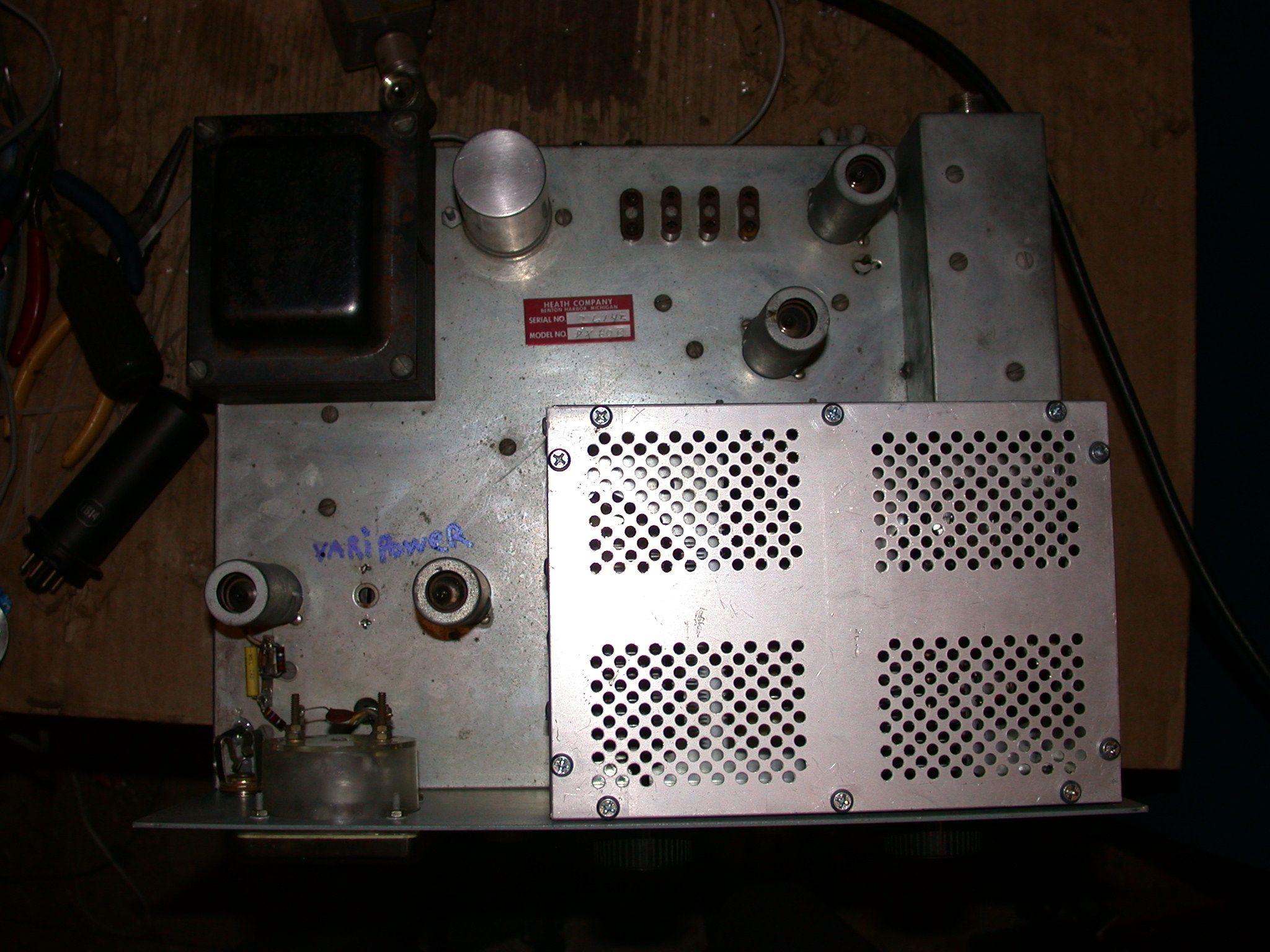
Timtron discusssed a neat vari-power circuit with me, but I did not get all the details at the time. I am not going to post something that isn't 100%
correct, so that is going to have to wait. Meantime, I am having lots of fun on AM and CW with my DX-60. I hope you enjoy yours as much as I do.
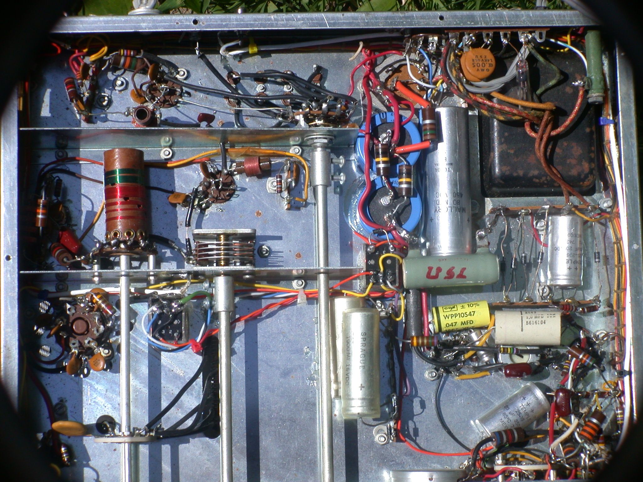
I had a long discussion with WA1HLR, Timtron, and tried to make a transcript of his take on how to improve the DX-60. What follows are his ideas, with photos and text.
This is not complete,
but I will try to finish as soon as I get the chance to get some clarification from him. I really need to use a tape recorder, because even a 20 minute old buzzard on
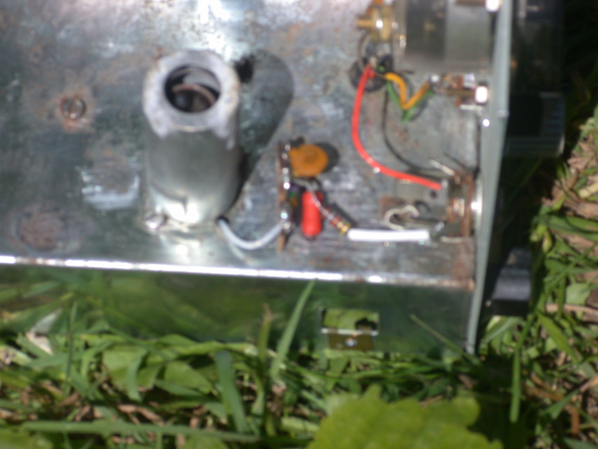
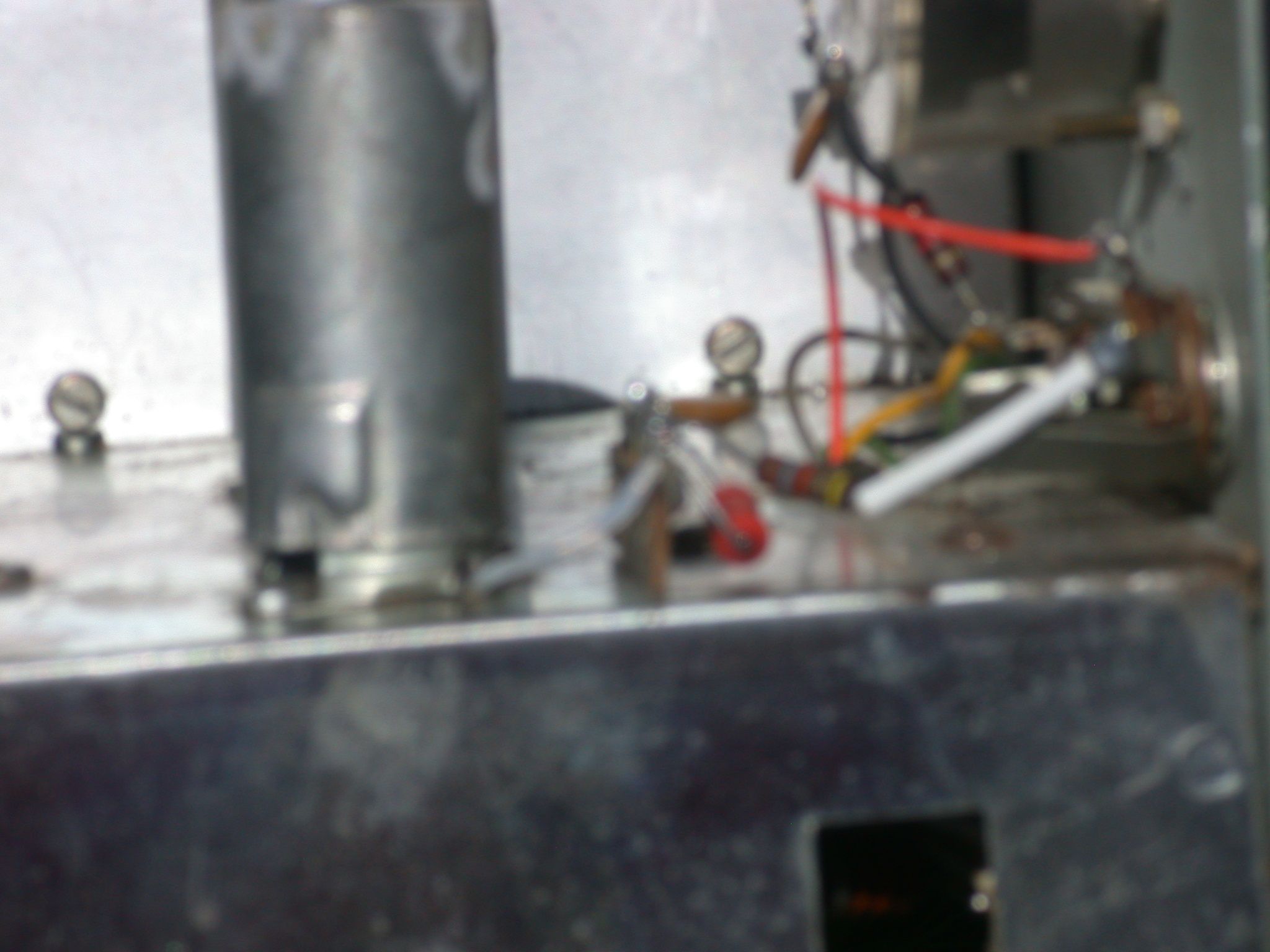
how to get rid of hnyellowy audio is very fast paced. The first step is move the mike jack topside on the chassis to reduce hum from AC and filament wiring.
An important element is to install ginormous filter capacitors to reduce hum. The other element is a clever vari-power circuit
which does not require the use of a 4 watt pot. (They are getting hard to find.) Stay tuned.
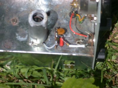
PUT R18, C30, C29, & R17 ABOVE CHASSIS 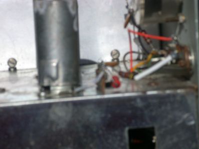
PUT R18, C30, C29, & R17 ABOVE CHASSIS 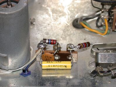
PUT R18, C30, C29, & R17 ABOVE CHASSIS 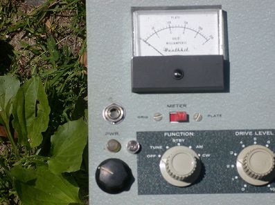
MIKE JACK & MODULATION POT |