|
Please don't just pirate this work without credit. I will keep these updated if you want to link to this.
UPDATE 1-10-2014: W1CKI full audio chain distortion reduction feed back circuit
I have just run across an inverse feedback circuit I have seen on the
web. It is a similar design to mine, uses the exact same driver
transformer, and tubes. It also does not need to raise the High Voltage power supply beyond the stock value, yet it still gets full modulation safely. It uses a feedback loop that includes both the driver transformer and the modulation transformer by carefully configuring phase shifts within the loop. Even if you do not do the mod, it is an informative read.
UPDATE 2-5-2014
I have been researching the feedback loop including the modulation transformer and found something at Electric Radio. I am referring to Electric Radio #203 and #204, the April and May 2006 issues of Electric Radio magazine. You can obtain copies of back issues at http://www.ermag.com/.
This modification is by far the best I have seen in print.
The mods articles are written by well known vintage transmitter expert Chuck Felton KD0ZS.
Here are its features:
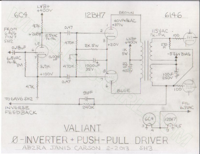
- Transformerless grid driver circuit. About the stock Valiant driver transformer, Chuck Felton states: "It is the worst thing you could have after a clipper; it's trash." You gotta love a man who calls it the way it is. However, it does not suffer the power limitations of the "East Coast" mods, since it is a low impedance driver. The 12BH7 driver for the 6146Bs is a cathode follower circuit.
- The clipper is retained for a modulation limiter to keep peaks from exceeding 100% negative.
- It can be configured so that the positive peaks can exceed 100%, using W8JI's suggestion of bypassing one diode with a capacitor.
- An overmodulation peak indicator is included in the design to allow adjustment of levels without having to have your scope on all the time. This will flash when you hit the baseline, telling you to back off just a tad.
- DC coupling is employed in some amplifier stages. Elimination of coupling capacitors extends low frequency response to zero Hz.
- A clever linear compressor keeps talk power up.
- Negative Feedback is applied around the modulation transformer, reducing distortion and improving bandwidth.
- It uses the stock High Voltage power supply to achieve full modulation.
Basic improvements to the Valiant include:
- Bias circuit adjustment pot mods for better range of adjustment.
- T/R relay improvements
- Improved VFO stability on higher bands
- Front Panel mike jack, which is something I considered to reduce hum.
- A fix to prevent failure of the fixed loading capacitors.
UPDATE 12-23-2014 ON TRANSFORMER AVAILABILITY
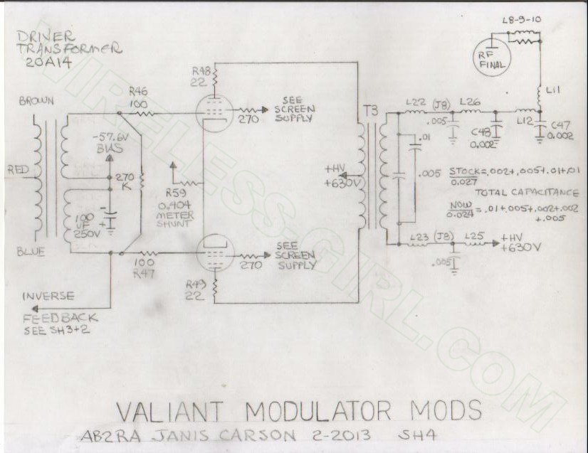
The Thordarson 20A14 used in this article is no longer available. I have received a number of inquiries about the interstage transformer used in this and some of the other mods. This update provides all the information needed to select and procure the right transformer for all styles of modifications.
Hammond makes an exact replacement the 124E. The specs are identical to those on the data sheet in this article.
You can read them at: http://www.hammondmfg.com/pdf/124E.pdf.
You can buy this transformer from the following places:
ADDITIONAL NOTE: If you want to do any of the mods like the W8JI or the TimTron mods and keep the single-ended stock 12AU7 paralleled cinfiguration, consider the Hammond 124B or the P-T156. The 124A is more like the original Valiant or other Johnson rig driver interstage, but for the small increase in price, buy the 124B and get better than original performance. The P-T156 works well and only costs $16.
If your Ranger, Viking II, Valiant, or other Johnson Transmitter burns out an audio interstage transformer,
this is the replacement that works perfect and fits the original bolt hole pattern.
It also would be perfect for a DX100 or Heathkit Apache.
This is a true high fidelity transformer. Read the specs at:
http://www.hammondmfg.com/124.htm.
Someday I will give one of these a try in a bone stock Valiant, if one crosses my bench.
Change the one capacitor W8JI calls for and install the P-T156 or 124B.
I think that will take it far enough that extensive modifications that I did or others did may be unnecessary
to get good performance. The W8JI and Timtron mods to the RF PA for correct biasing are necessary for any mod
to get the linearity with modulation correct.
| 
