|
I really like this new Ameritron ALS-1300 amplifier. I was debating whether
to go with a glass tube model like the AL82 or a ceramic external anode
tube model. The Chinese tube manufacturers and the QC problems they seem to
be having pulling full vacuum and life span of emission caused me concern.
In the end, I decided to go to fully modern solid state. I was not
disappointed!
I have seen the information for the coming new ALS-1306. I decided NOT to
wait for good reasons. First, getting even an exciter to work properly from
80 thru 10 was a challenge. Adding 160 and getting it right was a sign of a
better than average RF engineer. Adding 6 meters is getting more common now
we have FETs that can handle the power. But efficiency and stability trade
offs are not trivial. The ALS-1300 has been out for a while and all the
bugs seem to be worked out. I do not need that much power on 6 meters. And
the cost is more for something that I will not ever use. The ALS-1300 uses
all straightforward analog circuitry for ALC, SWR protection and keying and
control. The ALS-1306 has an embedded microprocessor to implement the lock out of 27 MHz signals. That added level of complexity makes repair more difficult, and includes parts that may become unavailable in a few years. "KISS" principal is the rule in my shack.
This preliminary posting has some photos that may be helpful to you
installing the 10 meter kit. Note the warning not to drive it with more
than 30 watts! Take this seriously or pay the consequences of connecting it
to an exciter set to 100 watts output. I contacted them and it is simply
and issue of the less drive needed to make full output. This is very
important if you have only connected a cable to key up the amplifier but
not implemented the ALC. Take my word, the ALC works very well and is
essential.
FAQs
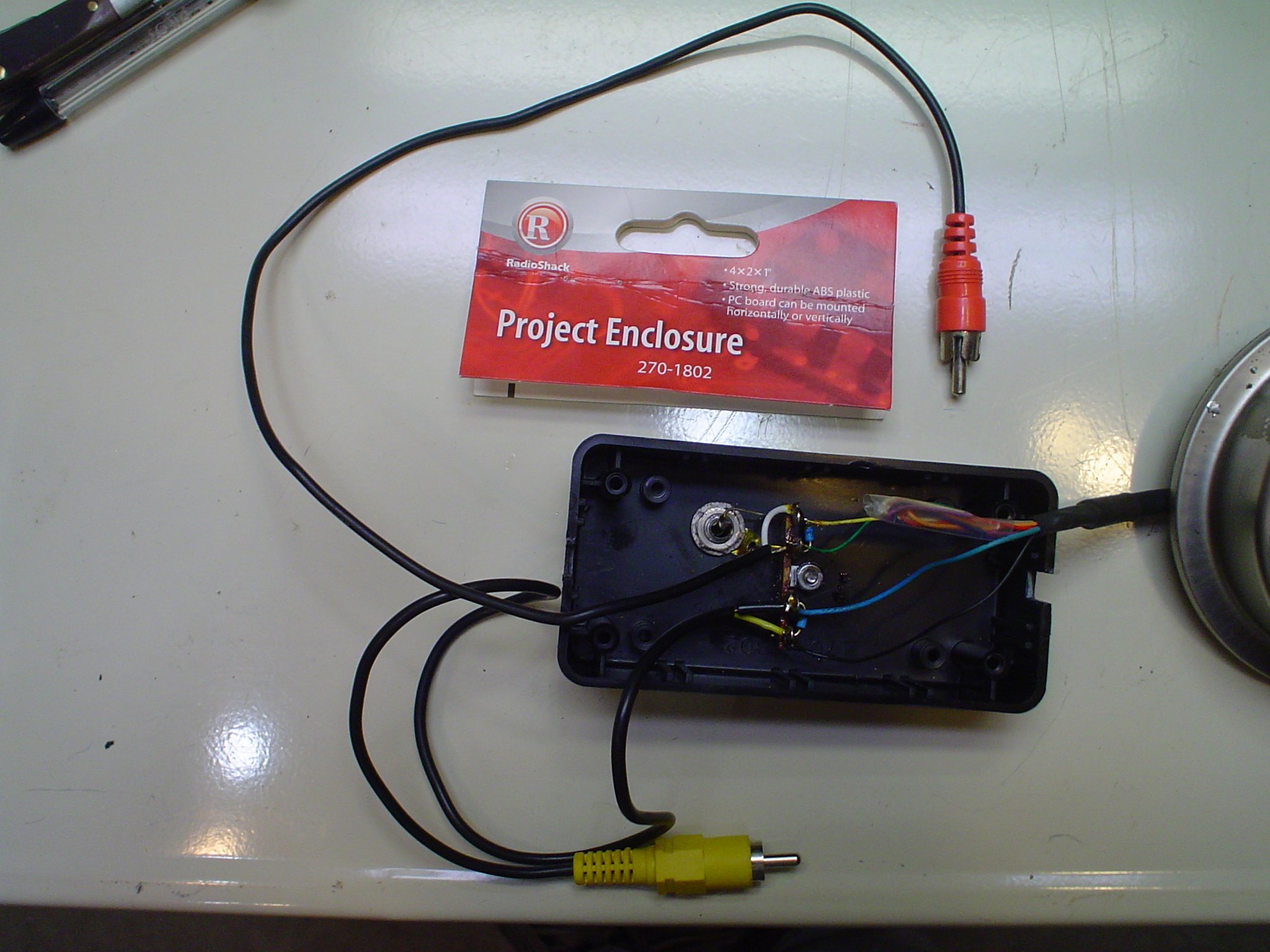
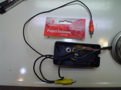
I built this interface cable. See the photo. The connector for the FT-950
linear amplifier port is getting hard to find. I was lucky to order one
early on. There is a guy on e-bay that makes them, with and without the
ALC. Get the one with both ALC and the keying line. I will have a full
print when I get the chance to scan it in, but it is probably easier for
you to buy the nice one on ebay. Gradually sneak up on the power from about
15 watts on any band. Once you reach full output, turn the ALS-1300 ALC SET
control from fully clockwise down a bit till the ALC light just starts to
come on and the ALC METER just comes up off the peg from zero. Do not be a
meter bender. The ALS-1300 will produce lots of clean power if you
correctly implement the ALC. The ALC is the only way the amplifier can protect itself by reducing the power using the ALC, in response to excess drive or high SWR. I know a lot of people do not bother with ALC, and often you can hear their splatter and buckshot well off frequency. Don't be one of "those guys".
Another protection item you should attend to is the AC power to the amplifier. Long ago, I installed a 30 amp 230 VAC line to the shack for my big iron rigs. It has a disconnect switch inside the shack. It is turned on only when I am operating. You hear reports of 12 volt power supply failure in these amplifiers. I have had this amp 3 years now, and have had no failures. I theorize that the failures occur when an AC line spike comes through due to lightning strikes or whatever. People need to disconnect all power to their station when not in use. I take this precaution for the 120 VAC lines to my rigs and the test bench. The AC powered lighting is the only thing that stays on, and there is an emergency DC backup lighting system in the radio room, in case the power goes off.
While you are at it, make sure you take precautions against lightning hits or induced surges against antennas. I use Alpha Delta switches in the antenna and station configuration (rig selector) system. I do remove the arc plugs from these. If you have significant SWR on the antenna side of your transmatch (such as an 80 meter dipole), the arc plugs WILL fire with full legal limit or even 500 watts output. Your tube gear may forgive you. Solid state gear may not. Repeated stressing of any solid state rig, regardless of internal protection circuitry, may eventually cause failure. The equipment does not know the difference between a lightning strike, sudden SWR increase, or an arc in the Alpha Delta arc plug. To remove them, unscrew the brass plug and invert the Alpha Delta switch. Catch the ceramic and metal "pill" in your other hand. Place it in a plastic bag stapled to the manual in your files, in case you ever want to re install it. Having the arc plugs back further in the switching system is pointless, and invites other mischief. They were a good idea, but they have their limitations. The only real protection from lightning is to disconnect the antennas OUTSIDE THE HOUSE and ground them separately from the house wiring and its ground. I have photos on my antenna section showing ground rods with bulkhead style coax connectors directly bolted to the ground rod. Of course, you have to seal the connectors against moisture. I also place a bucket from Lowe's over the whole thing, to provide shelter as well. In the event of severe storm or tornado warnings, I disconnect the coax to the house there, and roll it up near the house many feet away. If there is a hit, the only direct connection is from the antenna to the ground rod, away from the house. Leaving the antennas connected in any way to the power or radio systems, is a calculated risk I do not want to take. And the grounding function of the antenna switches is not a realistic protection, when you consider the thousands of amperes and volts available from a lightning bolt. If you like to operate during lightning storms, I wish you well in the afterlife....
Ameritron does not post ratings for RTTY or AM, nor does it even mention them in the operator's manual. That gives you cause to wonder if you can use it that way. This is an amplifier designed for light duty intermittent modes like CW or SSB. The math might make you think that you can use a 1200 watt PEP amplifier for 300 watt carrier AM. That is true for linear operation using the 4X the carrier rule. But that does not take into account the heat and power limitations of the devices and fans. The switching power supply is probably not up to the task. If you compare the older ALS-600 using the LINEAR (not the switcher) power supply, Ameritron states this (page 22 & 23 of the manual):
RTTY, FM and Other High Duty Cycle
The transmitting duty cycle, ambient temperature, supply voltage, fan speed and the load
SWR all play important roles in determining the transmit time limit on high duty cycle
modes. To minimize noise, Ameritron uses only enough fan speed to cool the ALS-600 for
typical amateur usage. If heavy duty cycle operation is planned, the following guidelines
should be followed. The output power can be reduced to assist with cooling. This is not the most effective
method of improving performance since the power must be reduced 5 times to cut the
heat dissipation in half. The exciter output should be restricted to a power level where
less than 200 watts output or 25 watts reflected power is obtained on long duty cycle
modes. The fan speed should be increased by replacing or supplementing the airflow from the
standard fan. A fan that delivers at least 80 CFM airflow at .l" of static pressure will
double the cooling and allow 500 watt RTTY transmissions with 2 minute on, one minute
off duty cycles.
Page 23:
The power supply high voltage output can be reduced to increase the efficiency at lower
output levels. At 30 volts the ALS-600 will deliver 275 watts of output power. This
allows a 100% duty cycle with any fan delivering more than 40 CFM at .08" of static
pressure, or a 5 minute on, two minute off duty cycle with the standard fan. Consult the
factory if you wish to reduce the high voltage output.level.
Either the exciter drive level or the amplifier "ALC SET" control can be adjusted to limit
the power output in the RTTY and FM modes.
AM Operation
AM operation requires that the carrier power of any linear amplifier be
restricted to one fourth of the peak envelope output power. With this amplifier, the maximum carrier
power on AM should be set for no more than 150 watts.
Proper modulation AM is indicated by observing the ratio of unmodulated carrier power
to the power indicated on voice modulation peaks. This should be approximately 4:1.
Never use the ALC to control the power on AM. The "ALC SET" control should be set
to the maximum clockwise position.
This would IMPLY that you could possibly run up to TWICE the ALS-600 rated 500 w RTTY (@ rated duty cycle) or 150 watts AM (@ rated duty cycle), if you made all the power voltage and fan adjustments stated. The ALS-1300 is just two ALS-600's in one box, with a power combiner, but it is the switcher supply. Even with the ALS-600, you cannot run it at these levels with the switcher supply. I have run my ALS-1300 at 100 watts carrier out, but no more, and the speed controlled fans did not change speed. I do not, however, make a practice of it; I sometimes use it to make a quick call to a friend I hear on on the air, but no rag chewing. I have a K7DYY full legal limit AM rig, a Johnson Viking 2, and a Heathkit DX-40 for that. I have not tried it on RTTY or digital modes yet. I plan to not exceed 250 watts RTTY ever with the ALS-1300. Increasing that to 500 watts gets you half an S unit, but with the lower power, you get more life from your solid state devices by avoiding excessive high heat power cycling. One reviewer uses his ALS-1306 on HF at 500 watts output, with the caution (read his info on the auto tuner not getting it to EXACTLY 1.000:1 SWR). He blew up his amplifier. He has switched to the Palstar AT2KD MANUAL TUNER. I have been saying that you HAVE to get this level of precision from your tuner with solid state gear ever since the beginning. Anyway, read this and decide for yourself:
ALS-1306 review:
http://nk7z.net/review-of-ameritrons-als-1306-amplifier/.
Palstar AT2KD Tuner review:
http://nk7z.net/review-palstar-at2kd-tuner/.
I plan to post a table with the power output measured with varying input
drive on various bands. Yes, the 10 meter band has somewhat less output
than the others. What amplifier isn't?
I studied the Ameritron interface box that links the exciter band switch to
the linear. Too much expense and complexity for me at this point. I did
goof and forget to sync the bands. The SWR protect quickly tripped and
protected everything nicely just like it should.
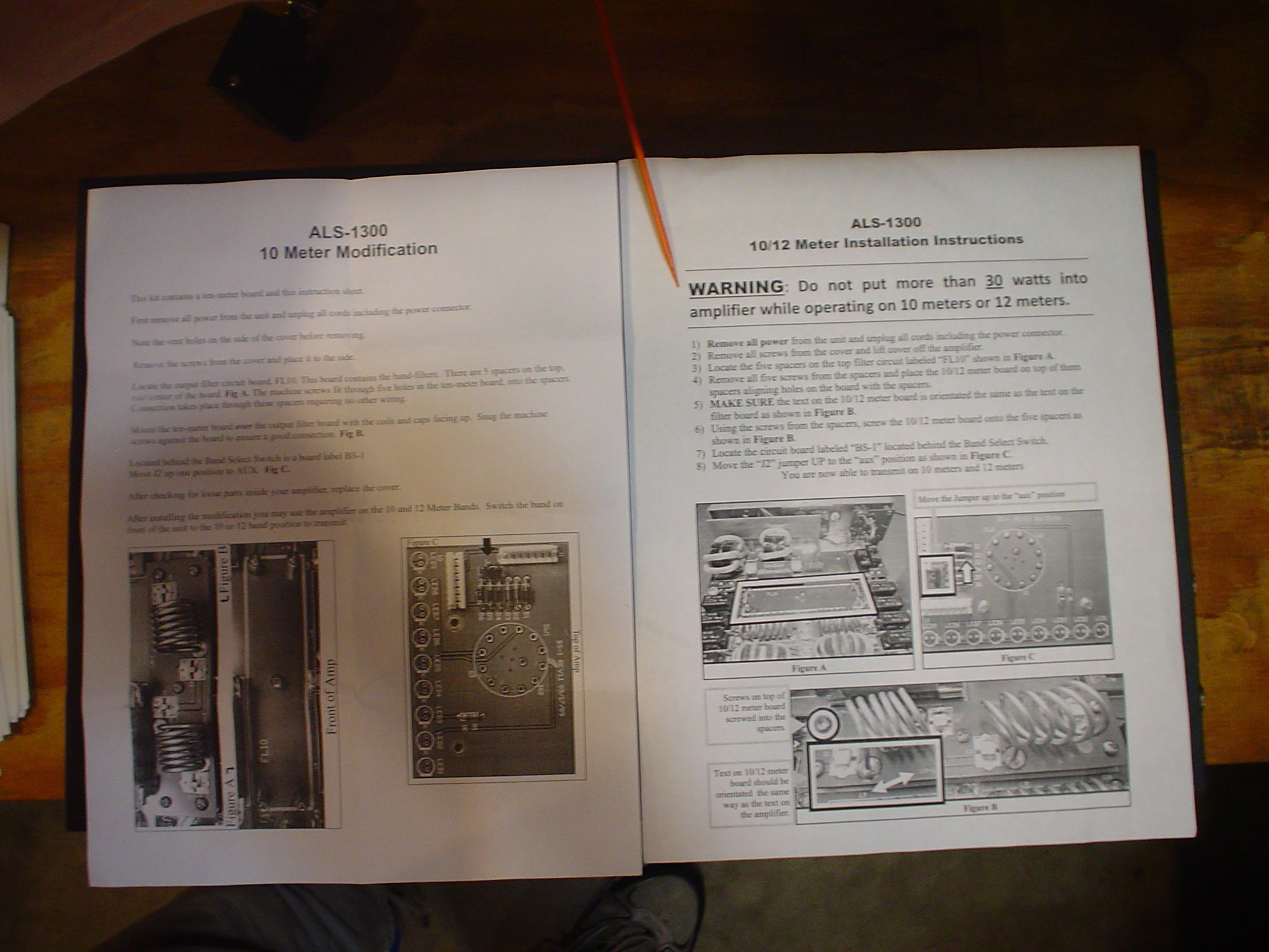
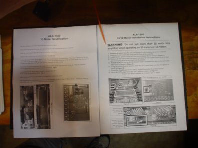
INSTALLING THE AMERITRON MOD-10 MK, 10 METER MODIFICATION KIT FOR THE ALS-1300
This part of the article assumes you have purchased the MOD-10 MK Ten Meter Modification kit and want to install it.
http://www.ameritron.com/Product.php?productid=MOD-10MK.
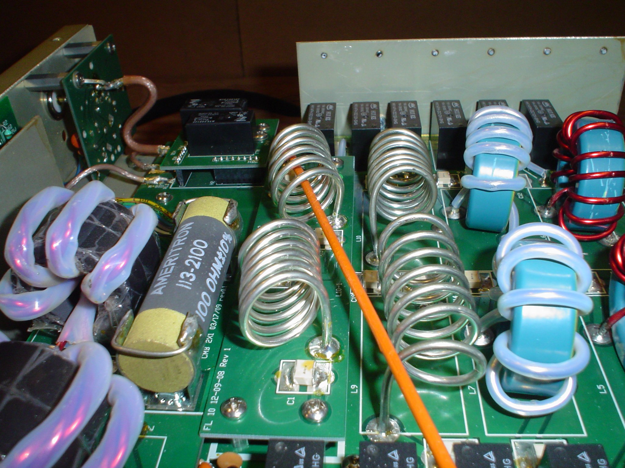
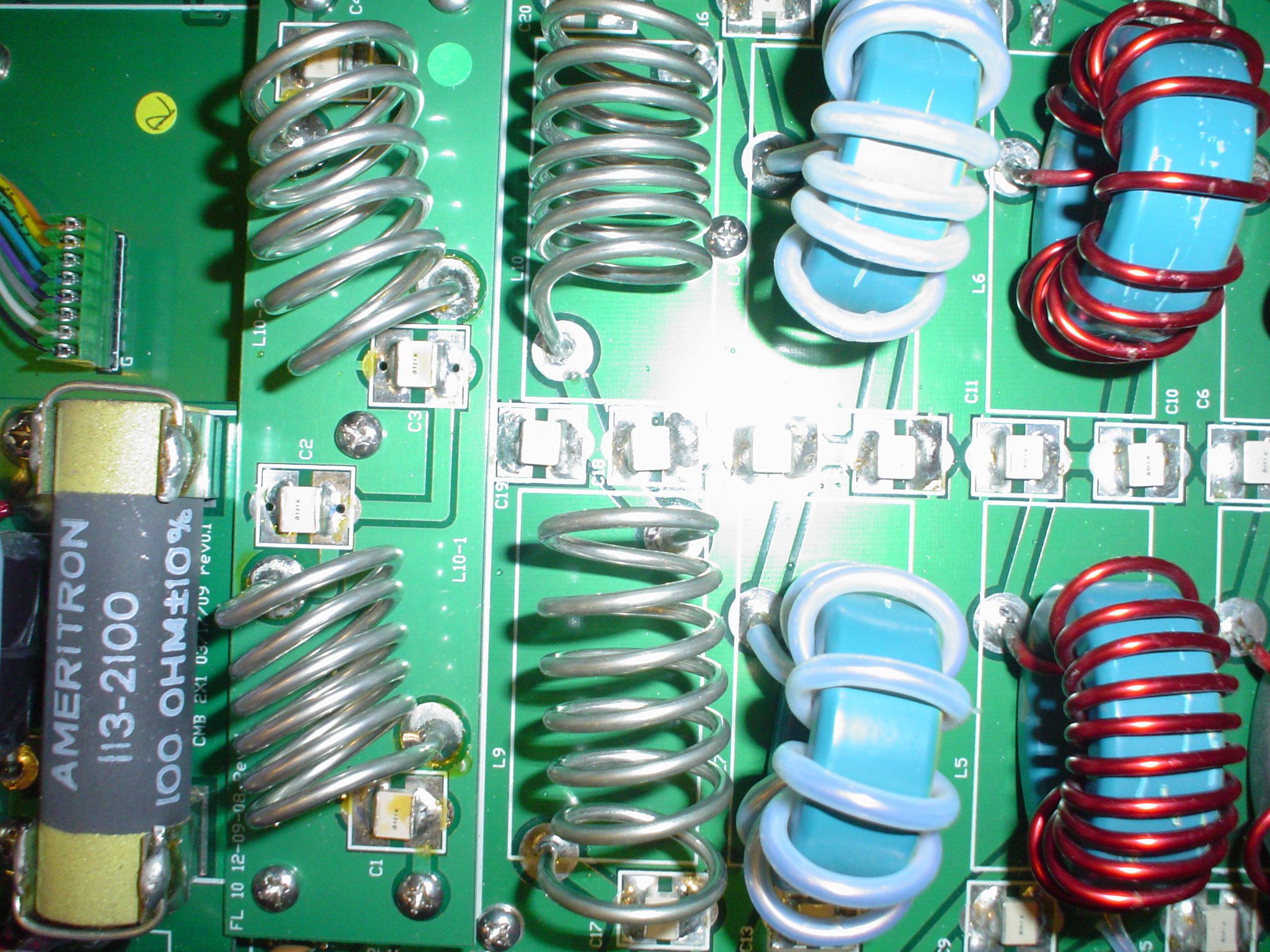
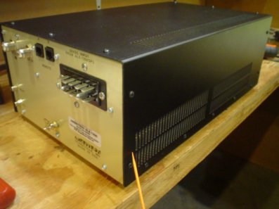
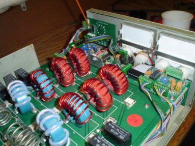
NOTE: I HIGHLY RECOMMEND PURCHASING THE ALS-1300X VERSION AMPLIFIER, WHICH HAS THE 10 METER MOD KIT ALREADY INSTALLED. If you present a valid FCC amateur license at the time of purchase, you can get this version of the amp. Normally, it is only available for export. If you look at the photos of mine, it was returned to the factory for repair. At that time, Ameritron tweaked all the band pass filters for best performance. The 10 meter coils look "squashed". That is done to tune them. The factory installed kit will have this done. There is no way you will be able to do this at home. But it beats shipping the amp back (not the power supply to save weight and cost).
The 10 meter mod is easy to install. The instructions have been updated to
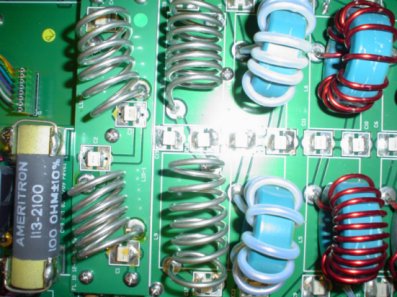
show the 30 watt warning. Also note that the coils are oriented at a slant
in the newer issue 10 meter mod kits. This is likely to prevent coupling
between the input filter section and the output filter section. This will
improve harmonic attenuation and smooth out filter response and bandpass
ripple. I wonder why they did not put one coil horizontal and one vertical.
It would have fit and probably worked better. However RESIST THE TEMPTATION
TO STRAIGHTEN OUT THE "BENT" COIL! Leave it alone and install it as shipped
per the supplied instructions.
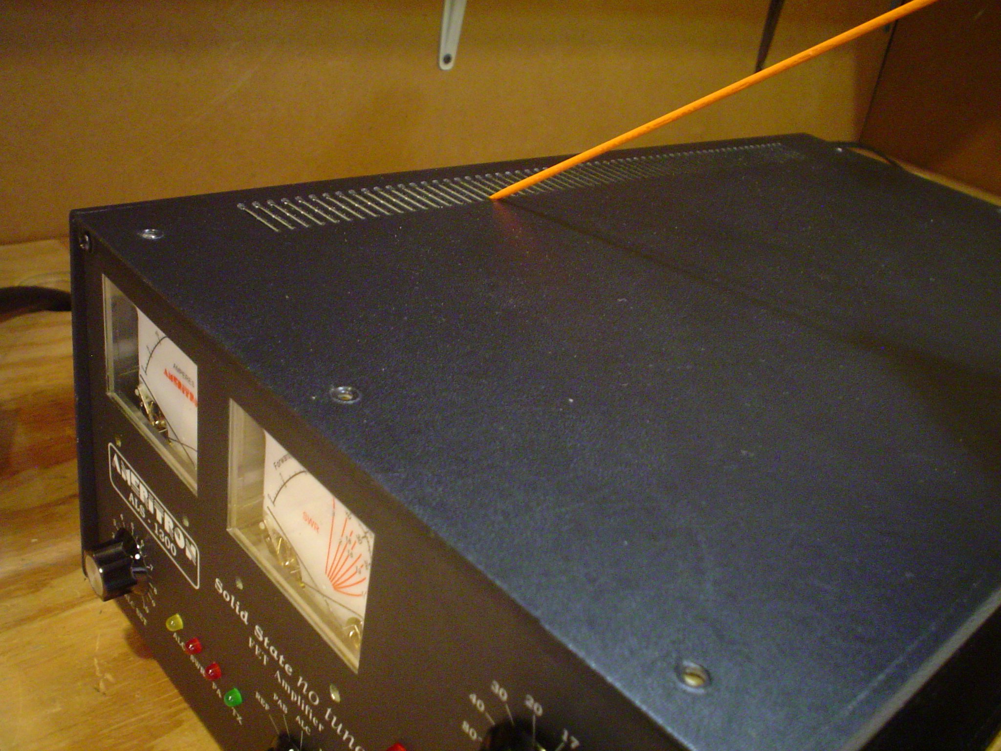
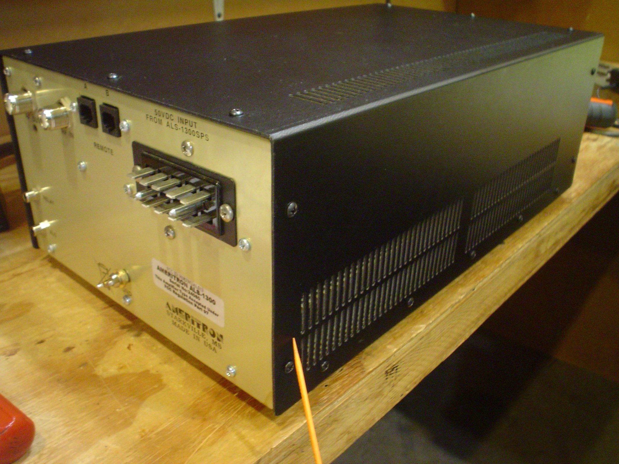
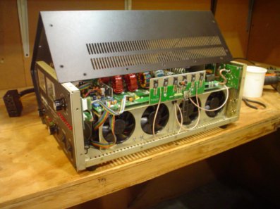
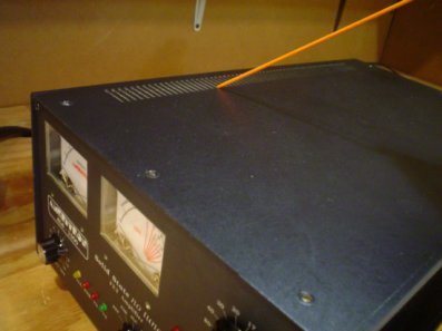
I have included some photos of the vent holes correctly installed. This is
important for cooling air flow. The cabinet can be installed rotated
incorrectly 180 degrees, but the fans will not line up properly. BE SURE
AFTER YOU INSTALL THE 10 METER KIT TO GET THE CABINET BACK TOGETHER IN THE
CORRECT ORIENTATION!
IMPORTANT NOTE: Reinstall the cabinet correctly with the vents in this position as
shown by the orange pointers. It will fit the wrong way but the fans will
not work properly if installed that way.
To see a youtube video, in English and Spanish of the installation, watch:
https://www.youtube.com/watch?v=MUYmRJ0FzVk.
I recommend that you buy as a spare the small board that contains the two relays that do the Transmit/Receive switching. It is located behind the 10 meter kit, near the coax connectors. It does not cost much. It gets cycled a lot. I would recommend some kind of add on QSK kit if you plan to run CW that way. I prefer a foot switch. When the T/R relay eventually fails, you will have one to restore operation immediately. There was a procedure to clean the contacts while transmitting at low power. Contact Ameritron to obtain that procedure. I am not going to spell it out here. I found that scary. You might not, its up to you.
I also recommend that if the amp has been idle for some time, you cycle the band switch a couple times, to clean the band switch relays, if you have problems that way. This is done while NOT TRANSMITTING. The relays will switch in receive mode just fine.
More to come, but for now, this is a nice piece of equipment and well done
at a good price.

|