|
One of the biggest problems for HF operators is the lack of a good wide band antenna for 80 Meters. I recently acquired a Yaesu FT-950, which has a built in transmatch which will handle 3:1 SWR. Further, my Johnson Valiant does not load directly into a standard dipole without a transmatch all the way across 80 meters. I got enough knobs to twiddle without adding a transmatch when going from CW to phone. It now works all the way without touching the coarse coupling at all from 3.6 to 3.9. It never results in a tuning solution that cannot be matched by the plate tuning or employs wide open coupling settings above 3. This indicates a well behaved low reactance load. Ditto for the Viking 2.
Also, since I cannot afford a tower, a good antenna has to hang from existing trees and can be launched with a compound bow with some surveyor's twine to pull up the supporting rope. I have put up field day antennas at 100 Feet using this method before. My trees have side branches, and I like to use a pulley to tune and service the antenna. So I had to settle for about 35 feet height, which is good for local work on 80 meters. I do have a high performance vertical for long haul stuff, but only engage it when talking outside the lower 48 states.
This article is meant to address this issue with a design that is mechanically sensible. I will first discuss some of the alternatives that have been offered over the years and lay out their flaws, and why this idea is better. My firmly held opinion is that if you have more than 3:1 SWR on your antenna, you need a new antenna. Also, using loss to obtain bandwidth is only a last resort. The typical G5RV is fed thru a balun (loss) and often 100 Ft of coax (often RG-58/U more loss) for field day, and people brag about how well that loads. Properly operated with no coax and a true balanced tuner like the Johnson Matchbox, it will perform OK. But if that's your style, this approach is not for you.
STANDARD DIPOLES, CENTER FED ZEPPS, TUNERS AND OTHER HASSLES
While many hams like open wire feed line to a flat top, there are reasons not to do it this way. First, I hate having to adjust half a dozen knobs to QSY and stress the finals with off resonance loading operations. Then there is loss in the transmatch, one or two dB. If you run coax to get through the wall of the house, add a balun, then go to open wire, add another one or two dB. Additionally the open wire line gets lossy and unpredictable when it is wet; coax does not. If the line is "hot" your computer goes nuts or there is RF on the mike causing distortion or other problems. Using coax to a standard 80 meter dipole with a 1:1 balun at full power and force feeding it at the CW end when the dipole is cut for phone will set fire to a W2AU balun in a hurry. A balun may work reasonably well into a resistive load, but adding it to a 80 meter standard dipole will surely abuse it, and also add loss in the form of heat instead of radiated RF. Get rid of the balun and you will do OK with a standard dipole on your favorite frequencies. Let the coax radiate if it chooses, or add a choke balun made of a coil of coax; at least you are getting RF instead of heat. But I like all modes, and I do not like slow QSY. Keep this in mind for field day when someone is putting a brick on the key for YOUR RIG to load into a G5RV and melts the finals. If you can only put up one antenna, I discuss the multiband Jetstream dipole approach. This article takes that concept to the next level, and compares the improvement in bandwidth.
BAZOOKA
The bazooka antenna is made from coax elements in the radiating portion of the dipole. First, it is mechanically undesirable due to the weight. Wind and support issues eliminate it immediately, and that is not the only flaw. Walt Maxwell thoroughly debunks this design. He shows that the losses in the coax pieces are the reason for the low SWR.
T2FD
The T2FD folded dipole similarly uses losses, this time in a resistor to obtain low SWR across the entire shortwave spectrum. Further, it employs a 12:1 VOLTAGE Balun. Voltage baluns are inherently inefficient, particularly into inductive loads. We can do better in nearly the same space, with less visual impact. The wife and homeowner's association will appreciate this approach better.
FULL WAVE HORIZONTAL LOOP
The full wave horizontal loop WILL give better band width than a dipole. At heights below 20 feet, it will outperform the dipole on local contacts, since it is a cloud burner. The dipole will have more ground loss than the loop. But for general purpose work at longer distances, it is not a good choice. Further, if coax fed via a ¼wave of 75 ohm line to match its higher impedance to 50 Ohms, it becomes a one band affair. The final product here is dual band 80 & 40 Meters with no compromise.
CAGE DIPOLES
Cage dipoles work by increasing the diameter of the radiating elements. Beam antennas use pipe instead of wire to achieve this effect, although Yagis can be fabricated from wire and hung from rope. The larger conductor lowers Q and increases bandwidth. Going from small guage wire to #12 wire reduces loss due to copper resistance losses, but it is not a significant enough change to add bandwidth to a dipole. A cage dipole typically attempts to simulate a wire diameter of 8 feet or so, and it works well. W1AW uses a cage dipole for 80 meters to keep its new solid state high power amplifiers happy. However, the mechanical problems of supporting such a structure in windy and icy conditions make it a project.
COLLINS DIPOLE
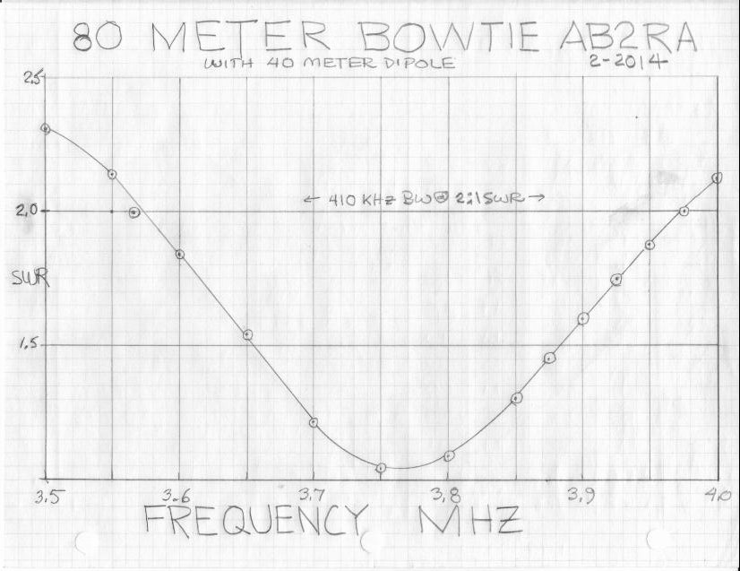
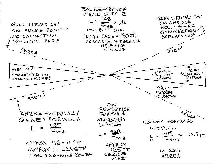
The so called Collins dipole was made popular back in the 50s as an answer to transmitters that did not tolerate more than 2:1 SWR. The 32V series was famous for damage to the L network fixed capacitors and associated loading switch. I changed a lot of them for friends. It is in the shape of a bowtie, and often included a balun. A recent article in Electric Radio magazine (September 2013) by Chuck Felton, KD0ZS got me to thinking about this idea. He achieved resonance at 3.8 with 1.2:1 SWR and 200 KHz between the 2:1 SWR points. The ends of the "bowtie" in his design are 9.5 feet apart. I wondered if spreading them further (say 30 feet) would be even better, and so here we go.......
THE AB2RA BROADBAND 80 & 40 METER BOWTIE DIPOLE
Referring to Figure 1, the antenna compares the design formulas and shapes of various broadband antenna designs. My formula comes from empirical work, not fancy math. But it should get you in the ball park, if your height is the same. Mine was at 35 Feet or so, and the impedance, while resistive, is lower than 50 Ohms as verified by my MFJ Antenna Analyzer. Your at resonance SWR will improve with heights of around 50 feet. If you go higher, the at resonance impedance will go to 70 or even 90 ohms, according to usual dipole impedance charts. Most of the Collins Dipole designs join the ends of the bowtie with a jumper that connects points on the wire that are theoretically at the same potential. I speculated that was unnecessary. Looking at standard UHF TV antennas using bowtie designs, they achieve wide band performance without any wire on the end; it is just a simple V on either side. Maybe adding a center wire so that there are three dipoles instead of two might help. I did not have conveniently located trees to explore this idea, and it worked well enough without it. I also had to fold one leg as shown in Figure 4, the "as built" drawing of the actual installation. If yours can be laid out straight, it will likely work better than mine. I tried to get all the wires the same length, but this is the way it turned out. Perhaps if you tune a pair to 3.6 MHz and the other to 3.8, you will get even better results. If the pair is 90 degrees apart, the tuning interactions might not be as much, and it would allow omnidirectional coverage. I suspect the at resonance SWR would be closer to 1:1 at 70 to 100 feet. I leave this to the folks with design software and more room on their lots.
This antenna is easier to erect than the T2FD, cage dipole, or Collins Dipole. There are no spreaders. It is just 4 wires connected to a center insulator. A center support is preferable to bear the weight of the coax. I use the best center insulator available, all stainless hardware, from the Wireman. I use Coax-Seal or Duct Seal from your local electrical supply house to seal all coax connectors. Allow enough slack to allow the trees to sway in the wind. Chuck Felton's design was an inverted V to allow attachment of the 160 Meter element to be attached without the use of a ladder. I have a good 160 Meter Loop, and only needed 80 and 40 to add to it. So I put the ends as high as I could get them. Typically, bandwidth is better on a standard dipole compared to a V, all other things being equal.
THE PROOF OF THE PUDDING
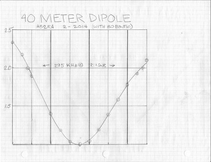
Refer to Figure 3 BOWTIE 80 METER SWR to see the final result. The MFJ Antenna Analyzer reads significantly higher than the panel meter on the FT-950 and the other meters I have, so I suspect that it is better than shown. The 950 is happy with its internal tuner memorizing various settings. The Valiant also is happy. Below 3.6, I use 0, 1 or 2 on the Coarse Coupling. From 3.6 to 3.9, it likes 3. From 3.9 to 4, it uses 1 or zero. There are no spots that cannot get a good dip on the plate tuning or employ coarse loading wide-open which would cause harmonic radiation.
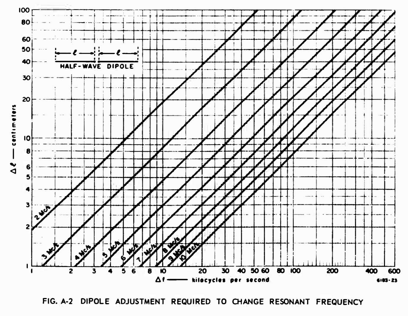
Back in the day, the miltary had really good tech schools. A soldier in the field did not have time or calculators and had to get the job done. Here is a chart from a Field Guide to antennas prepared by Stanford University for Project
Agile. It even has a page in it for modding the BC-610. Basic antenna theory has not changed a bit from that time, other than having better computer modeling. If you want to get your station up and running with an effective antenna, use this chart to prune for best SWR, on just one try. Later, I may add nomograph lines for 14, 18, 21, and 28 MHz. Click on the chart to enlarge it. Print it out from there if you find it useful. For now, this chart is same as the original published at:
http://www.dtic.mil/get-tr-doc/pdf?AD=AD0684938.
Or if you would rather use a calculator, Don AC2RS has developed a tool for pruning dipoles in one step.
See it at: /Projects/Antennas/AntennaCalc.html.
THE 40 METER ADD-ON
I added a 40 Meter element. Nothing changed on 80 meters. In the SWR charts, I compared it to the Jetstream Multiband 80 through 10 meter dipole this antenna replaced. See Figure 2 for the raw data. See Figure 5 for the SWR curves for 40 Meters. The 40 Meter antenna that was part of the Jetstream was adjusted for phone optimum. It did provide operation with a tuner on 15 Meters. The new antenna for 80 & 40 only was set for midband on 40, and it delivered 2.4:1 all across 15 Meters, and the Yaesu and Valiant loaded it with no external transmatch required. I did not count on this, but it solved the problem of 15 Meters nicely. I suspect the 20 and 10 Meter elements complicated the 15 meter operation. Hey, it works with this length of coax (about 100 Ft to the radio). Your mileage may vary.
Some Measurements:


NOTES
My article on this was published in Electric Radio (http://www.ermag.com/) issue #308 January 2015.
For a mathematical approach to follow up, see QST February 2015 "The Doctor is In" page 67.
That author does a EZNEC analysis of this same concept using stagger tuned dipoles at 90 degree angles which provides a W shaped SWR curve and full 3.5 to 4.0 with less than 2:1 across the entire band. This approach achieves all that a cage dipole promised without the mechanical complexity. He also covers some of the folded dipole and coupled resonator approaches to broadband dipoles which have equal mechanical complexity.
Speaking of math, if you eliminate the antenna tuner and buy some good coax from JefaTech:
(link: http://www.jefatech.com/category/d100-ll400,
review: http://www.eham.net/reviews/detail/9735)
you get the convenience of no knob QSY, no weather worries due to rain and ice, and less mechanical hassle than open wire, at a lower price by eliminating the tuner with equal performance on feedline loss.
5/29/17 UPDATE: BROADBAND DIPOLES STAGGER TUNED TO 2 FREQUENCIES WORK BETTER THAN BROADBAND DIPOLES WITH EQUAL LEGS
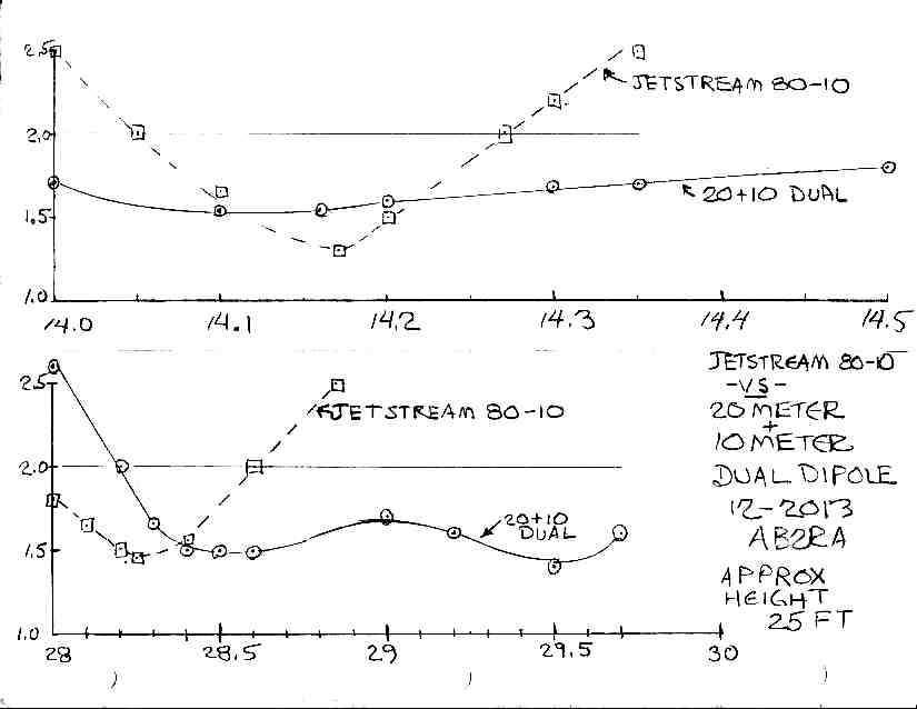
An August 1968 QST article by Howard W4RZL, republished in ARRL Wire Antenna Classics First Edition, was in the back of my mind as a possible improvement to the 80 meter broadband dipole I already had installed. It agreed with my findings that the Collins Broadband Dipole (with equal length wires) 12 foot end spacing did not perform as well as might be expected. The W4RZL research showed 20 to 40 feet spacing at the dipole ends and different dipole lengths was significantly better. W4RZL also used a multiband scheme for 40 and 20 along with the 80 meter dipole. Building it with multiple bands makes each band narrower. You can see the curves for 20 and 10 meters comparing the dual band and Jetstream all band dipoles below.
Neither the W4RZL nor the Collins Dipole had the severe mechanical disadvantages of the so called "Cage Dipole". Both were equal to or better than the Cage Dipole in SWR performance.
As part of my routine spring service on all antennas, I took it down and measured it. I was not satisfied with the tuning and measurements I had done in haste with an approaching winter.
This spring, I took the antenna down, and chose the longest dipole and added bare wire of about 15 feet to it, to tune it way below the ham band. This allowed me to characterize the resonant frequency of the shorter dipole. Then I gradually shortened the longer dipole, making it approach the frequency I wanted. Unless the dipoles are perpendicular, the tuning of the two dipoles will interact. If the two dipoles are tuned to 3600 and 3975 as suggested in the W4RZL article, there is a W shaped SWR response that could peak in the center of the band that approaches or exceeds 2:1. I tuned mine to about 3900 and 3650, to lower the mid band SWR peak. I wanted the very best SWR on phone, with improved response on CW over a regular dipole. This in no way demeans the work of Collins or W4RZL; I just wanted a different result. The Antenna Classics also has a dipole with only one wire element, but uses reactive elements to obtain broad band response. I just like the simplicity of this design shown here.
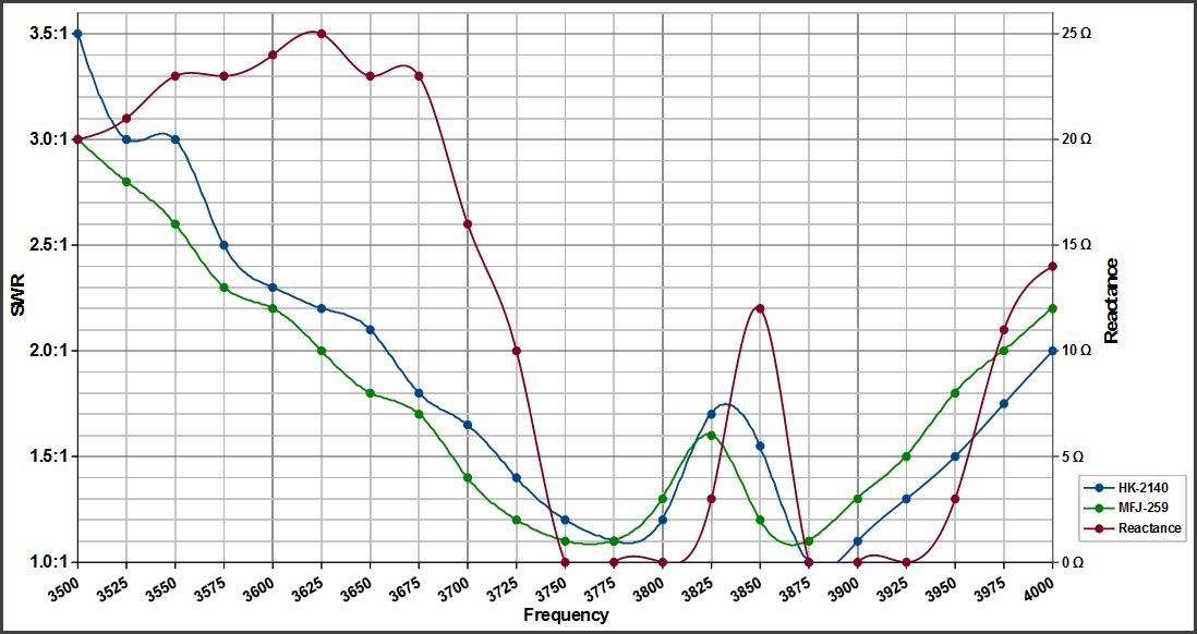
I also used a couple of measuring methods. One was a standard SWR/Power Meter made by Heathkit, the model 2140. I really like this meter, and with care during calibration, the peak reading function even works pretty well. For an inexpensive meter, that is unusual. The second method of SWR was the MFJ 259 Antenna Analyzer. That one was calibrated using the methods detailed on the W8JI website. Both of these correlate pretty well. The MFJ also provided Resistance and Reactance (no sign displayed on my older model). The Zero Reactance points on the SWR graph are very enlightening. These are true resonance points which would be picked up by a grid dip meter. W4RZL uses a Millen GDO in his article. W4RZL also does not use a balun, and tries his design with a variety of feedline lengths; he found that his design was relatively independent of these factors. It is also noteworthy that the reactance does not go above 25 ohms over a 500 KHz band width; over much of the phone band, it does not exceed 15 ohms reactive. Large amounts of reactance is what solid state rigs and amplifiers do not tolerate well. Being able to operate directly into an antenna without the added loss of a tuner is well worth the work. The Dentron MT-2000A specifies 0.5 dB maximum loss at match condition, one of the few who actually publish it. It is one of the best out there, and much more rugged than the Ten Tec 238, which also claims low loss.
I did not include the resistance measurements as they would just add another layer of confusion. It wandered around 35 to 40 ohms, expected at the 45 foot height. Anyway, here is what I got in the real world, measured in the shack where my equipment was located. That is where it really matters to me. I am not going into antenna models (with all their assumptions). What kind of ground you have at your location will influence the final results. What really matters is what your radio sees, not thetas and betas. I do plan to put a ground reflector under this antenna later. I will update this site with more data if that is significantly different from what is shown. A ground reflector theoretically will improve the efficiency, especially at near vertical angles. I am always thinking ahead to the next improvement. But for the time, here is the actual measured SWR of the present antenna. You can clearly see the W shaped SWR curve resulting from two distinct points of resonance, unlike the original data posted here. Also the new SWR band width at 2:1 was 350 KHz instead of 300 KHz. The center "hump" was 1.7:1 or less. I was trying to get good SWR at 3705, 3837, and 3885. That turned out pretty good. I may even try it with a 40 meter dipole later.
THE 20 & 10 DUAL BAND DIPOLE
Since I had removed the Jetstream style 80 through 10 higher bands, I needed coverage of the bands on a separate antenna now. See Figure 6 for the improvement of the dual band configuration from the Jetstream multiband configuration. This is the result of my first attempt, a dual band 20 and 10 meter dipole fed from a common feedline. DO NOT attempt to use a 15 or 17 meter dipole with this combination, since it will detune both of the other antennas. You can see the improvement from separating the 20 and 10 meter dipoles from the 40 meter dipole; the SWR band width is dramatically improved.
[Raw Data: Dual 20 & 10 vs Jetstream]
At some point, I had new anchors installed in the trees. So I installed the 20 meter dipole at 35 feet, and the 10 meter dipole at 30 feet. I used SEPARATE FEEDLINES, so that these were individual "stacked" dipoles at optimum height. WOW! The new SWR curves are below. Keep in mind that the "jetstream" all band configuration, the dual band configuration, and the separate individual configuration ALL deliver monoband performance. But the SWR now allows completely tunerless operation on all of the band in each case. This experiment is intended to demonstrate to you that IF you have the space and supports for individual dipoles at optimum height, operation is easier. If you do not have the space or supports, the performance is compromised in subtle ways as this experiment proves.
Most commercial antennas specify their band width at the 2.0:1 frequencies. On 20 meters, these monoband dipoles measure 2:1 at 13.380 and 14.775 for a band width of 1.395 MHz. For 10 meters, the frequencies are 27.265 and 30.336 for a band width of 3.071 MHz. This is for thin wire elements, not large aluminum pipes. I defy you to find ANY commercially made antenna that delivers that kind of SWR curve, without the use of lossy resistive components like the T2FD, lossy bazooka trickery, or smoke and mirrors advertising. Significantly, the reactance curves show very little of this component. The resistive portion is NOT 50 ohms, since an optimal height dipole is more like 70 ohms, but most radios cope pretty well with resistive loads, especially if they are a little HIGHER than 50 ohms. Many verticals deliver LOW resistive loads (because they are shortened by traps or loading coils) at resonance, which is tolerated less by solid state radios.
Once again, build your own, save money, and get better performance!
THE 20 METER MONOBAND DIPOLE

THE 10 METER MONOBAND DIPOLE

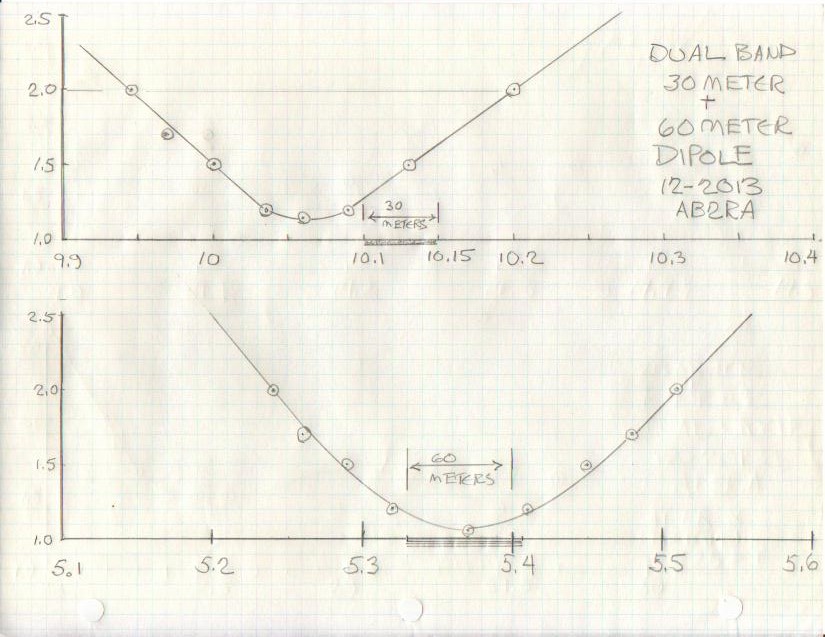
THE 60 AND 30 METER DUAL BAND DIPOLE
The original Jetstream Multiband 80 - 10 Dipole never had coverage of these bands. I put up another separate dual band antenna for the new bands, now that I had a rig (FT-950) that covered them. See Figure 8 for the SWR curves.
WHAT ABOUT 17 AND 6 METERS?
I think you can do this if you optimize the 6 meter performance as a 3/2 wave and take what you get for SWR on 17 meters. I saw something on the web that did this OK. I put up separate dipoles for these bands, since they are small and inexpensive. The percentage bandwidth on 6 meters is 8%, which is pretty wide, if you plan to use CW, SSB and FM. It is nearly as big a challenge as 80 Meters, so I decided to keep it simple. I may try a bowtie style design on 6 Meters or maybe a bowtie on 17 Meters and see if the 6 Meter 3/2 wave harmonic is similarly wide band. If you give it a try and it works, let me know.
UPDATE 6/10/2015
This addtional information is in response to an e-mail query about this page.
Wireman is about the same price for center insulator as the inferior ones.
All stainless hardware, drip ring, better braid to attach, workmanship excellent.
Ductseal from local electrician supply (brick about $5 for lifetime supply) seals coax connector and is easily removable.
Cheaper than the sealing wrap that is the exact same material.
PVC pipe will work fine.
I buy the pipe caps to keep the hornets from making nests in them.
Also keeps water out so doesn't de tune.
I drill a small hole in the bottom to drain water which may enter as it travels on the wire thru the spreaders.
You can buy a long piece of PVC and cut it into the various lengths with a sharp hacksaw. Deburr it so the end caps can be removed if necessary.
I recommend 4 ft at the ends if you can manage for between the 80/40. The wider spread, the less interaction and more bandwidth.
Then at the 40/20 half that length (2 ft spreader) and the 20/10 will be 1 ft.
Make some intermediate spreaders or it will tangle in the wind.
PVC is very light, but might consider #12 ga wire for strength.
One other approach if you have room is to do the broadband dipole on 80/75 with separate wires to separate trees about 20 ft or more apart. Better SWR curve on 80 and maybe helps 40 too.
Then do just a 40/20/10 with the multiband in the middle of the two branches of the 80/75.
One center pulley and coax for all of it.
If you want a multiband antenna for cheap (don't have to buy a tuner and GOOD open wire aint cheap) that will match or be better than the conventional G5RV this is the bees knees. Easier on your radio too.
Jetstream kit does not space antennas a far apart; only 6 inches. Same deal for the Alpha Delta.
Lots of interaction between various bands.
Still gonna need a tuner at the band edges unless you cut it for phone or CW and only do one mode.
I use two separate end ropes to the same tree on my installation on Long Island from the 80 and 40 antennas.
I put the 20 and 10 on the INNER part of the spreaders to keep them tensioned.
That way nothing flops in the wind.
This method went thru Sandy without a scratch.
I wind a 6" of bare stranded wire around each antenna wire as it passes thru the spreader to keep it from sawing back and forth in the wind and keep the 20 and 10 meters from losing tension due to slipping toward the center gradually.
Drill as small a hole as possible for the wires in the spreaders to keep rain and bugs out.
Lay out all the wire on the lawn near the final location and feed the spreaders onto the wire toward the center, then wrap the anchor wires on the spreaders. Rewrap the 6 " anchor wires tightly once you get it all tuned.
15 meters is a "bonus band" that will require a tuner. The length of the 50Ω coax may help or hinder a match. Try inserting a short length jumper (3 ft) to see if the rig's built in tuner will match. The 3/2 wave 15 meter antenna (really the 40 meter dipole) has significant gain and is about 150Ω resistive depending on height. It is essentially a coax fed G5RV scaled for best performance on 25 meters.
For how to build information, construction details and material sources for this project, see my article:
Building Dipole or Wire Antennas.
|