WHY THE MULTIBAND HF FAN DIPOLE IS THE RIGHT CHOICE, IF YOU CAN ONLY PUT UP ONE ANTENNA
There are many choices for hf antennas. Your station
has specific requirements that may not match mine. I am sharing here
the thought process and experimentation that I went through to arrive
at the solution that best fits my needs. Many assert that THEIR
antenna is the BEST, with a sort of religious fervor. You may find
some of my work useful and applicable to your purposes.
Here are the design criteria I used to select the
antennas I use at various locations:
- COST.
This is a hobby, and I need a better used car more than radio toys.
I am retired.
- The
antenna should not require an extensive ground counterpoise. While
a do have a no-compromise ground system under one of my vertical
installations, I do not wish to dig up the yard on Long Island.
This eliminates most verticals and end fed wires. Also, aluminum
pipe antennas are out of my price range, often contain traps
(although there are some good ones out there that don't), and do not
provide the high angle radiation needed for local work on bands
below 11Mc.
- Minimum
visual impact. I have no problems with restrictive deeds and
covenants, but wish to keep our country settings less “industrial”.
So, no towers. Maybe a push up mast. But pipe is expensive.
- Traps
are lossy to some degree, regardless of manufacturer's claims to the
contrary. Others have tested this, and there is no need to
duplicate their work here. The inductive portion of the trap also
serves as a loading coil, shortening the needed length of the
antenna; but it also reduces bandwidth. I should note that I do
have a trap vertical, and it works well on 75 meter DX and 40 DX,
but it is completely unsuitable for local ragchewing. I have
components for a trap dipole, but the bandwidth and loss eliminated
them quickly during initial experimentation. No traps, anywhere.
- Baluns
of various types are available. Transformer baluns have inherent
loss. Choke baluns are not quite as lossy, and can be helpful in
maintaining a clean radiation pattern and keeping RF out of the
shack. As long as my antenna radiates roughly according to the
published patterns, I do not need a “textbook” pattern.
The “carolina windom” in fact uses this very feedline
radiation to obtain its performance. Even though the Carolina Windom has a balun, we used one for Field Day, and I was pleasantly surprised with how well it did, and how easily it was to install; it did not cover all bands, and it did contain a Balun, and it was fairly expensive by comparison to a multiband dipole. I do not know if it was a voltage balun. I have a W2AU voltage balun that was
given to me for failure analysis. Someone tried to “force
feed” a dipole on 80 meters away from its resonant frequency,
and literally set the case on fire. W8JI has done some analysis of
baluns: No baluns anywhere, with the possible exception of a choke balun.
- Open wire feeders are popular with the ham community once again. The
“old school” handbooks of a bygone era have lots of
configurations for you to try. They require the use of an antenna
tuner. The demands on an open wire rated antenna tuner are much
greater than a “coax line flattener” type tuner. The
SWR on an open line can be very high, and the currents and voltages
can be impressive, due to the range of impedances encountered.
Further, the problem of feedline radiation and RF in the shack can
be daunting. Finally, while the radiation patterns are OK for lower
bands, the upper bands can be plagued with annoying lobes and nulls
that are too complex. No open wire feeders, except possibly as a
match section.
- The
ubiquitous G5RV is rejected for the same reasons, along with the
proven fact that adding 100 feet of lossy RG58 with a high SWR and
force feeding it from an antenna tuner just plain doesn't work. I
have used this antenna on field day and swore: never again. IF you
put it up at 70 feet, and use open wire all the way to the shack, it
can work well. But then its just another multiband flat top center
fed Zepp. The trick is that the 105 foot length makes it a 3/2 wave
gain antenna on 20 meters. This explains why some operators swear
by it. But for all the reasons noted above, this is not my antenna.
- The
standard single wire fed Windom is also rejected because it works
against ground, has excessive feedline radiation, and excessive
nulls and lobes in the pattern on upper frequencies.
- Reliability
and consistency of loading is a must-have feature. I constantly
hear hams on the air grousing about rain and ice detuning their
tuned feeders, resulting in arcing and damage to transmitter
components. Again, no open wire or single wire feeders.
- Any
antenna chosen MUST exceed safety standards for RF exposure. Open
wire feeders and single wire feeders are rejected for this reason
also. You can get away with this stuff with QRP. I use QRP, but
with a full performance antenna. Asking someone to dig you out of
the QRM because you haven't done adequate antenna installation work
is lazy, unless you have to do a stealth installation.
I have an EFJ KW Matchbox, Heathkit SA2060, Dentron MT2000A, and a
homebrew L-C-L version of the Murch ultimate transmatch (which
provides a low pass function useful for running legacy gear while
meeting current spurious emission standards). All of them work
nicely. I also had a Ten Tec 238B which is the subject of another
article. The 238 was rejected as unsatisfactory and sold at a
hamfest after testing found that the match range on 160 and 80 meters
employing the stock fixed ceramic disc capacitors was inadequate for
my needs. You may find it just fine for your purposes, and an
article referenced in my rebuild article on the 238 uses doorknob
capacitors to overcome some of its deficiencies. Further, unless you
go to a fan dipole for extra bandwidth on 80 meters, you are going to
have to have some sort of matching network. A fan dipole for the
final application that is described here would be mechanically
complex, and less likely to stay up in an ice storm. So, a GOOD
tuner is OK, and likely necessary. The built in tuner in most good
modern solid state transceivers is adequate to match this antenna
without the use of an external matchbox. I cannot afford modern
equipment, and enjoy restoring older gear, so this is not a
consideration in my case.
There is the T2FD, a B&W design still employed by
the government. It provides low SWR over a wide frequency range. It
is excellent for automatic link establishment. It also is good for
novice operators who are learning radio, to avoid damage to a
transmitter by accidental misadjustment. I had one in Long Island
for just that reason. However, due to the resistive loading employed
to get the bandwidth, there are losses. There are pro and con
discussions out there on the internet. Check them out for yourself,
and decide. I found that I gave up 1 or 2 S units, except on 15 and
17 meters, where the antenna did OK. Also, its expensive. If you
can only put up one antenna at your location, wish generally mediocre
but easy to adjust performance, this might be a good match for you.
I wanted something better.
GOOD GRIEF! WHAT'S LEFT?
The full wave horizontal loop is a good performer as a “cloud
burner” for local work. In fact, the separate Loop article on
this page shows my 160 meter loop antenna. But it is not a good
general purpose antenna, contrary to the claims of some information
out there. I wanted some DX performance, and at the low heights I
was employing, that was not working out, by actual on the air tests.
Another popular “old school” antenna is the
multiband fan dipole. It works by feeding a group of separate
dipoles for each band from a common coaxial feedline.
I have trees. A pulley for the center is up about 45
feet. This is an effective height for 40 meters and up. It also is
up high enough for 80 meters for local work. Recent analysis shows
that the sandy soil on Long Island favors low angle radiation at
lower heights than “perfect earth” to a small degree.
Listening tests confirm this initially. I will have to do some more
testing on the air. I am optimistic that I will be able to use this
antenna for DX work to Europe on 75 Meters this winter from Long
Island. It probably will not outperform my vertical upstate, which
uses up about a half a mile of electric fence wire for the ground
system.


CENTER (LEFT PICTURE) AND ONE SIDE (RIGHT PIC) OF DIPOLE UP IN TREES,
ALMOST STEALTH INVISIBILITY.
CAN YOU FIND THE SPREADERS
IN THE RIGHT-HAND PICTURE? IF NOT, CLICK HERE.
PARTS – WHERE TO GET THEM, WHAT IS BEST VALUE?
You can buy the wire in bulk from the Wireman.
Copperweld is sturdy and long life, and cuts nicely to formula. Not
easy to find it locally. Maybe the hamfest.
You can buy the wire from Lowe's. I like #12 THHN,
which comes in spools of 500 ft for less than $50. But insulated
wire does not cut to formula. Generally, I cut it to formula length,
and wind up removing about 1% to 5% more from the ends because of the
installation. Black wire is good for stealth. It does add weight.
Pure Copper can stretch. Also, I use some of the bare wire to wrap
around the spreaders to anchor the spreader in place. I am not sure
how that would work out with insulated wire. Comparison shop, and
make your choice, based on your needs, but those are the
considerations you should weigh.
I really like the Wireman center insulator. Type 801,
CQ Dipole Center – Stainless Hardware, tinned COPPER braid,
good quality SO-239 and insulation, all for ONLY $12.95!! Further,
it has a lowered lip at the bottom of the insulator, where the coax
attaches. This provides a drip ring that keeps water out of the
coax. [insert pic of center insulator here]


BALUNS ARE INDICATED IN SOME CIRCUMSTANCES, NOT HERE.
THE WIREMAN 801 CQ CENTER INSULATOR IS MUCH LIGHTER, AND ALL YOU NEED.
I SOLD THE BALUN TO A "TRUE BELIEVER" FOR $15 AT A HAMFEST, REDUCTING THE COST OF THE PROJECT.
YOU CAN BUY COAX SEAL FROM VARIOUS SOURCES, BUT ELECTRICIAN'S DUCT SEAL FROM HOME DEPOT IS JUST AS GOOD, AND REALLY CHEAP FOR A WHOLE BRICK! ITS FUNCTION IS TO PROTECT THE CONNECTION FROM WATER AND CORROSION, WITH GOOD DIELECTRIC PROPERTIES.
X-Treme tape is an easy to use product that many prefer to keep water out of coax connectors:
https://www.amazon.com/gp/product/B00HWRORX0/ref=ppx_yo_dt_b_search_asin_title?ie=UTF8&psc=1
For more tips on quality components for antennas, see:
http://www.wirelessgirl.net/Projects/Horizontal-Loop/Construction.html
IMPORTANT: SEE W8JI SITE FOR HIS REVIEWS AND TESTS OF COMMERCIAL BALUNS WITH REAL TEST EQUIPMENT NOT GUESS WORK. IT WILL MAKE YOU A HERETIC LIKE ME! I DO NOT PULL ANY PUNCHES ABOUT THE DEFICIENCIES OF BALUNS AND OPEN WIRE LINE HERE, AND NEITHER DOES HE.
The W2AU ANSulator (basically a PVC center insulator
without the balun) is also OK. But no drip ring, and about the same
price.
If you are really cheap, you can make your own, but I
cannot imagine why. Unless you make one with an integral spreader.
[reference needed] PVC at the center is probably adequate for the
impedances encountered with this style of antenna.
Use coax seal, or Duct Seal (available at electrical
supply places like Lowe's) to cover the coax connector, and you have
a really reliable center connection. Radio Shack sells small
quantities of it, but you can get a whole brick of the stuff for 5
bucks at Lowe's.
The spreaders shown are made from standard PVC ½
inch pipe from Lowe's. I used the standard cap to keep the water out
of the top, and bugs out of the bottom. Drill a weep hole in the
bottom one only to let any water out that leaks in from the wire
holes. You can use them for all the spreaders. I wound up buying
the Jetstream, which includes the spreaders. The spreaders are too
small, except for use at the center of the antenna, which I explain
later.
Alpha Delta and Jetstream sell multiband fan dipole
kits. The Jetstream uses a voltage balun that looks OK for 40 Meters
and up, but W8JI does not review it. It has separate connections for
the dipole wires, compared to the W2AU which uses the same screws for
internal connections. I did not saw one apart to confirm the size
of the core, but it probably is comparable. The Alpha Delta uses a
heavy center insulator which has “lightning protection”
but no balun. The lightning protection should be at the ground level
where it can attach to a protective ground rod system, not add weight
at the center to create mechanical problems. The Alpha Delta dipole
wire isolation system looks nice in the catalog, but I did not
examine one up close due to the price. I am not sure how the length
is adjusted for tuning. The Jetstream is a deal. The spreader
insulators provided are OK for the center of the antenna, and even if
you do not use the balun, the wire provided makes it worth
purchasing. The Jetstream system can be had for about $80, if you
look around. I plan to unload the balun at a hamfest, but used all
the other Jetstream components.
The Jetstream installation instructions for length come
out about right (see below). The internet article on multiband dipoles has some
good tips as well. [reference needed] I advise making the antenna
longer to start with, and removing wire as needed to get resonance.


Download as .cbr file
The loading effect of the nearby wires is reduced by
homebrew PVC insulators shown. I have 4 foot spreaders on the ends
at the 40 meter end point. The insulators are 2 foot and one foot as
they taper in. If you build it with the stock Jetstream insulators,
the tuning gets very touchy on the upper bands. The Long Island
antenna shown is the second version, much improved. The article
above noted comments on the minimum spreader length needed to get
good performance, and I followed that advice to advantage. [insert
pics of spreaders here]


DRILL A SMALL HOLE IN THE BOTTOM ONLY FOR DRAINAGE OF MOISTURE. LEAVE THE TOP CAP CLOSED.
Incidentally, I did not use the cheesy plastic end
insulators included. They are probably OK, but I went to ceramic
ends for the 80 and 40 Meter elements. I tend to run an amplifier on
these bands. Plastic end insulators deteriorate with weather exposure over the years.
I like the MFJ-16C06 insulators. Six in a pack for dirt cheap. I do
not like to patch up a compromise installation later. There are
times when a little more money spent at the initial time of
installation saves headaches later.
IMPORTANT NOTE ON ORDER OF ANTENNAS INSTALLED ON LONG SPREADERS.
You can get a significant improvement in mechanical
stability by avoiding the Jetstream order of dipoles. They use, from
top to bottom, 80, 40, 20, 10 Meters. I use 80 on top, 10 next, 20
lower, and on the very bottom 40 Meters. This allows me to stretch
the 10 and 20 Meter elements tight, to avoid shorting between the
elements at the smaller inner spacing. Also, the 40 Meter element
can be pulled tight to tension the other elements and avoid whipping
about in the wind, which causes metal fatigue and failure. Tuning is
more stable in the wind this way. My antenna in Long Island, in this configuration,
survived hurricane Sandy in 2012 with no damage.

MY ANTENNA USES THE LOWEST FREQUENCY 80 METER (LONGEST) ON TOP.
THE NEXT LONGEST 40 METER IS ON THE BOTTOM FOR BEST STABILITY IN WIND AND STRENGTH.
20 METERS AND 10 METERS ARE MECHANICALLY BETWEEN THE 80 METER TOP AND 40 METER BOTTOM.
WIRE LENGTHS SHOWN ARE FOR CW & PHONE CENTER BAND. USE THE JETSTREAM DATA SHEET PROVIDED.
15 METERS WORKS WITH A TUNER AS A 3/2 WAVE GAIN ANTENNA, FROM THE 40 METER ANTENNA.
BUILD AND ADJUST YOUR DIPOLE TO CORRECT LENGTH FOR BEST SWR IN JUST ONE HOISTING
This tool is better than the Jetstream data. It also allows you to get pretty good first cut measurements if you choose to use your own THHN stranded insulated wire and PVC spacers. Please keep in mind that this tool was developed for INDIVIDUAL DIPOLES ON SEPARATE FEEDLINES. There is interaction between the various antennas in the mulitband dipole. For that reason, do not combine a 160 dipole with anything other than a 80 meter only. The resonances repeating at 2 MHz intervals will make obtaining resonance difficult at best. MY method separates the dipoles much farther than either the Alpha Delta or the Jetstream, or any of the designs you find in the antenna handbooks. This assumes that you use only antennas with a 2:1 frequency ratio. In other words, do NOT try to add to a 80/40/20/10 any other antennas. Specifically do NOT install a 15 meter wire or you will mess up 20 and 10. Also, do NOT add 60 or 30 meters to a 80/40/20 multiband antenna; do a separate multiband antenna with its own feedline for that. In fact, you are better off installing a multiband 80/40/20 and making other arangements for 15 and 10, as well as 60/30/15, and separate installations for 12 and 6 meters, for best performance and bandwidth. As the frequency goes up, it gets much more tricky to get multiband antennas to coexist on the same feedline. THIS TOOL WILL GET YOU TO THE BEST ADJUSTMENT A LOT QUICKER THAN YOU WOULD HAVE DONE WITH CUT AND TRY. Adjust the lowest frequency band first, then move up through the spectrum to the maximum frequency. With that caveat, I now offer you a slick tool too make your first cut and subsequent adjustments in an efficient manner.
Click here to use the Calculators for Making your Own Wire Antenna written by Don, AC2RS.
The following procedure works for full wave loops, half wave dipoles, and quarter wave verticals:
- First, if you haven't already done so, cut your own dipole wires to slightly longer than that required by the lowest frequency in the band of interest using the first calculator on Don's page.
- Then, measure the actual frequency of minimum SWR (and zero reactance if you have an MFJ antenna analyzer).
- Plug those numbers into the second calculator to find out how much to adjust the length.
- Let your antenna down JUST ONCE (if it was up yet), adjust the length, put it (back) up, and you are done!
The third calculator on Don's page is a tool for determining correct length of a quarter wave transmission line of 75 ohm coax (RG-11/U from DX Engineering) to transform the 150 ohm nominal full wave loop impedance to 50 ohms for tunerless fun. This tool can also be used to calculate the right length of 75 ohm line to transform the third harmonic operation of a 40 meter dipole for 15 meters. The short length of match section in that case would have minimal effect on the 40 meter operation. I have done this, and it works! The hats or stubs added at approximately 11 feet out from feedpoint can also shift the resonance lower in the 15 meter band without dramatically influencing the 40 meter resonance.
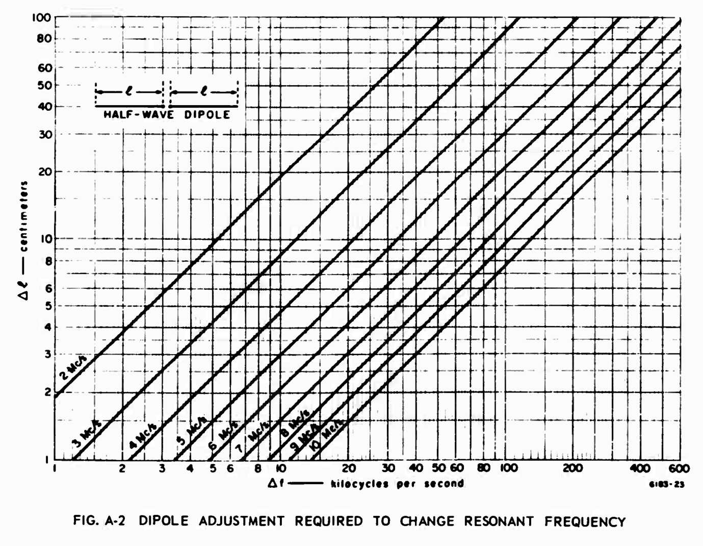
Back in the day, the miltary had really good tech schools. A soldier in the field did not have time or calculators and had to get the job done. Here is a chart from a Field Guide to antennas prepared by Stanford University for Project
Agile. It even has a page in it for modding the BC-610. Basic antenna theory has not changed a bit from that time, other than having better computer modeling. If you want to get your station up and running with an effective antenna, use this chart to prune for best SWR, on just one try. Later, I may add nomograph lines for 14, 18, 21, and 28 MHz. Click on the chart to enlarge it. Print it out from there if you find it useful. For now, this chart is same as the original published at:
http://www.dtic.mil/get-tr-doc/pdf?AD=AD0684938.
Or if you would rather use a calculator, Don AC2RS has developed a tool for pruning dipoles in one step.
See it at: /Projects/Antennas/AntennaCalc.html.
WHAT KIND OF FEEDLINE SHOULD I USE?
Do not, unless you simply cannot afford anything else, use RG58. It's too lossy.
A friend uses RG8M or RG8X to reduce the weight at the
center, and uses a coupler to get to RG213 or the newer low loss
cable once he gets to the ground. This is an OK compromise, if you
have no center support.
I have a center support at a good height, which is where
you need it. If necessary, you can use an Inverted Vee fashion for
this antenna, but I advise RG213 or better all the way to the shack,
and a center support, in this case a mature Oak tree.
REALLY IMPORTANT MECHANICAL STUFF
I used a climber to install a good quality pulley at the
apex for service. The ends also have pulleys for adjustment of
tension and resonance. Agway had better quality pulleys than Home
Depot.
Also, I used THHN wire for the pulleys, to avoid
squirrels gnawing through support ropes that I could not reach.
Replace any worn supports BEFORE they fail by taping replacement rope
or wire and using the old support to pull the new stuff up. I have
heard Franks Red Hot Pepper Sauce is a good deterrent if you soak the
ropes. I prefer a friend with a 22 rifle, if only for the
gratification it produces.
Orient the antenna properly for a pattern that reaches
the most of the populated world. My antenna runs from Northwest to
Southeast. Broadside radiation favors Northeast (Europe) and
Southwest (USA and Australia). It seems to hear OK into South
America as well. But I live in the Northeast US. USE A GREAT CIRCLE
MAP, not a Mercator projection, to determine correct beam headings.
You will get all messed up if you do not observe this precaution.
This orientation does not “see” Japan well.
But its an Inverted Vee in my case, so testing may reveal it is not
so bad. Put up a second antenna at right angles to get all the
areas. Its cheap enough, and a good antenna switch is a lot cheaper
than a rotator and tower.
Why anyone spends that kind of money on a tower and
rotatable (shortened) dipole is beyond me. Yes, maybe if you already
own a tribander and tower.
With a dipole at a good height, full length, no traps,
you will get slightly less performance than a compromise trap
tribander for a whole lot less money and hassle. About an S Unit.
Make that up with a speech processor or smarter operating techniques.
No building permits. No conspicuous tower and metal in your yard.
Good results from your QRP rig with a proper antenna.
I used a ground mounted Gotham vertical with no radials
downtown as a novice back in 1959. I nearly gave up the hobby
because of it.
This full size, full performance wire antenna fits
diagonally on a 100 foot wide suburban lot.
BUT WHAT IS THE SWR LIKE?
Lets face it, you are going to need a tuner to get to
the band edges on most any antenna you employ, particularly on 80 and
40. With a tuner, you can use this on 15 meters as a 3/2 wave gain
antenna with a good pattern. Its feedpoint impedance is about 150
ohms nonreactive at resonance on 15 meters. This transformed to 20
ohms at the shack end of 100 feet of RG213. Your results may vary,
but these are well within the matching range of any good antenna
tuner design. Other bands show about 50 ohms at resonance.
An MFJ 259 was used to make all measurements, and trim
the wire. You can do it with an ordinary SWR bridge too, but its
more tedious. I was given my MFJ as a “rescue” unit that
was about to be discarded after it was damaged during heavy use. I
repaired it and calibrated it for less than $20, using the techniques
on W8JI site. Thanks, Natan, it has been a very useful gift.
The SWR will vary with wire nearby, whether you use a
metal push up mast, height above ground, and other considerations. I
will not publish the results here, as it would only duplicate the
work of others. The only comment I will make is that it is typical
of any good MONOBAND dipole installation, IF you use the LONGER
spreaders to improve the Jetstream design's shorter spreaders.
Avoidance of lossy components delivers monoband
performance from a multiband installation. It nicely meets or
exceeds all the original design criteria. This antenna is well worth
your effort to install.
BUT WHAT ABOUT THE WARC BANDS?
This antenna depends on a 2:1 frequency separation to
operate correctly. The second harmonic of any antenna represents
thousands of ohms across 50 ohms center impedance.
Incidentally that is why you do NOT use a 15 meter
element on the antenna I show. You take what you get on 15 meters
and tune it. As a bonus, you get a gain antenna with a pattern
oriented in the directions of service chosen, not a bunch of random
lobes.
The Jetstream antenna I received had enough leftover
wire that I could build another separate antenna for 30 Meters and 17
Meters. This provides the requisite 2:1 frequency ratio. It does
not mess up the good performance of the existing multiband dipole.
Trying to tune that with these elements is an exercise in
frustration, even with good equipment. It is likely also to
compromise performance.
Buy a second Wireman center insulator and other supplies
to complete a WARC band capable dipole.
You could also build a 18 Mc and 24.8 Mc unit. However,
a 10 Mc unit combined with a 24.8 Mc dipole would likely fail,
because that is an approximate 3:1 frequency separation.
THE BOTTOM LINE
The Jetstream Multiband Dipole Kit
is a good value, and has all the parts you will need for an all band antenna installation,
except for the center insulator. Add ceramic end insulators and PVC
wider spreaders to improve it, and get on the air. This is also a
great beginner's antenna. You can get it from CheapHam.com or click on Jetstream's dealers link; they do not sell directly.
For how to build information, construction details and material sources for this project, see my article:
Building Dipole or Wire Antennas.
UPDATE 6/10/2015
This addtional information is in response to an e-mail query about this page.
Wireman is about the same price for center insulator as the inferior ones.
All stainless hardware, drip ring, better braid to attach, workmanship excellent.
Ductseal from local electrician supply (brick about $5 for lifetime supply) seals coax connector and is easily removable.
Cheaper than the sealing wrap that is the exact same material.
PVC pipe will work fine.
I buy the pipe caps to keep the hornets from making nests in them.
Also keeps water out so doesn't de tune.
I drill a small hole in the bottom to drain water which may enter as it travels on the wire thru the spreaders.
You can buy a long piece of PVC and cut it into the various lengths with a sharp hacksaw. Deburr it so the end caps can be removed if necessary.
I recommend 4 ft at the ends if you can manage for between the 80/40. The wider spread, the less interaction and more bandwidth.
Then at the 40/20 half that length (2 ft spreader) and the 20/10 will be 1 ft.
Make some intermediate spreaders or it will tangle in the wind.
PVC is very light, but might consider #12 ga wire for strength.
One other approach if you have room is to do the broadband dipole on 80/75 with separate wires to separate trees about 20 ft or more apart. Better SWR curve on 80 and maybe helps 40 too.
Then do just a 40/20/10 with the multiband in the middle of the two branches of the 80/75.
One center pulley and coax for all of it.
If you want a multiband antenna for cheap (don't have to buy a tuner and GOOD open wire aint cheap) that will match or be better than the conventional G5RV this is the bees knees. Easier on your radio too.
Jetstream kit does not space antennas a far apart; only 6 inches. Same deal for the Alpha Delta.
Lots of interaction between various bands.
Still gonna need a tuner at the band edges unless you cut it for phone or CW and only do one mode.
I use two separate end ropes to the same tree on my installation on Long Island from the 80 and 40 antennas.
I put the 20 and 10 on the INNER part of the spreaders to keep them tensioned.
That way nothing flops in the wind.
This method went thru Sandy without a scratch.
I wind a 6" of bare stranded wire around each antenna wire as it passes thru the spreader to keep it from sawing back and forth in the wind and keep the 20 and 10 meters from losing tension due to slipping toward the center gradually.
Drill as small a hole as possible for the wires in the spreaders to keep rain and bugs out.
Lay out all the wire on the lawn near the final location and feed the spreaders onto the wire toward the center, then wrap the anchor wires on the spreaders. Rewrap the 6 " anchor wires tightly once you get it all tuned.
DIPOLE FOR 40 AND 15 METERS WITH MATCHING SECTION FOR LOW SWR ON 15 METERS
15 meters is a "bonus band" that will require a tuner. The length of the 50Ω coax may help or hinder a match. Try inserting a short length jumper (3 ft) to see if the rig's built in tuner will match. The 3/2 wave 15 meter antenna (really the 40 meter dipole) has significant gain and a decent pattern (not a malaria germ) and is about 150Ω resistive depending on height. It is essentially a coax fed G5RV scaled for best performance on 15 meters.
For my monoband 40 meter dipole in Ithaca, I plan to add a brief section showing how to use a quarter wave matching section on 15 meters to provide a low SWR. This matching section is so short that it does not interfere with 40 meter operation. Do not try that with this multiband dipole or you will mess up 20 and 10 meters. Various articles are out there on using short stubs hanging a quarter wavelength out from the feed point on 40 meters, to improve resonance on 15 meters. These stubs will likely tangle with the other antennas on this multiband dipole, so there is no good way other than a tuner to get this to work. Fortunately, the 15 meter third harmonic resonance of the 40 meter dipole is not excessively reactive. I plan to try my 40 meter single band dipole as a combination 15 meter fan dipole; the stubs may not be necessary in that case. I am suspicious of all these stubs hanging from a 40 meter dipole. W6SAI did an article in CQ that used "hairpin" two wire shorted open wire stubs at the same location. He claimed a low SWR on 15 without a coaxial matching section. That configuration is worth a try. I believe that the stubs, about 13 inches, function more as a trap in that case. Whether you still get the 3/2 wave gain from that is open to question if that is true. Stay tuned for another update.
I know all the street wisdom is that you cannot combine a dipole with another dipole with a 3:1 frequency range. NOT SO! I did it, it works, and I publish the results here. You just cannot put a 15 meter dipole on the same feedline with a 20 and/or 10 meter dipole without very quirky resonance problems. The true reason for the 40/15 caution just disappeared in the legends of the past. You could also get good 15 meter SWR with a 60/30/15 meter combination, which I may try later. In the case of my 40/15 fan dipole, you need 30 degree angle separation to get good performance. The SWR is less than 1.2:1 all the way across the 15 meter band, with independent adjustment for 40 meters. For further information on the 40 and 15 meter multiband antenna, please see my other article, The 40 and 15 Meter Dipole - a Myth Exposed.
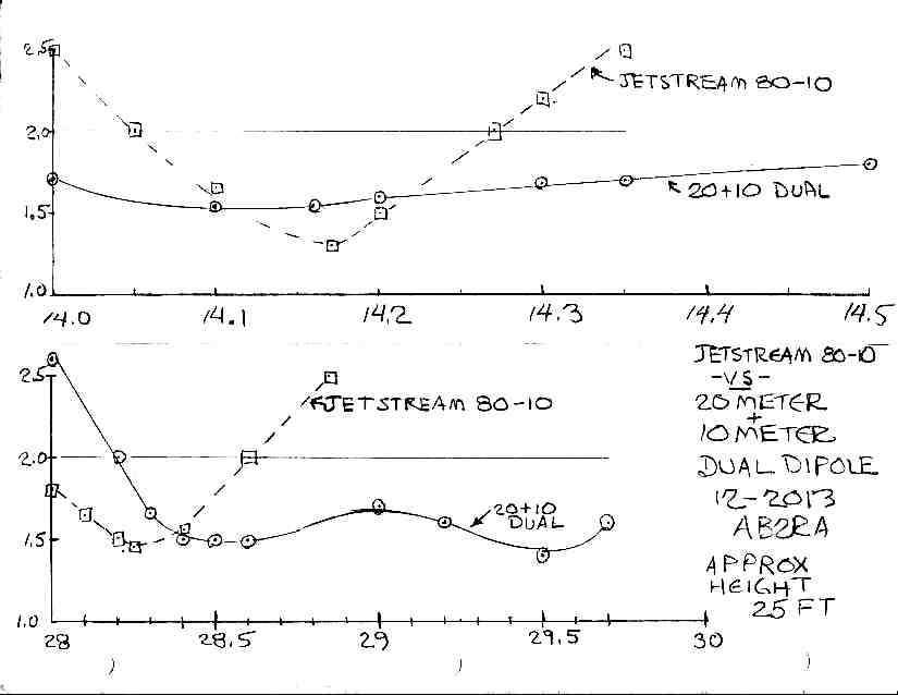
THE 20 & 10 DUAL BAND DIPOLE
Since I had removed the Jetstream style 80 through 10 higher bands, I needed coverage of the bands on a separate antenna now. See Figure 6 for the improvement of the dual band configuration from the Jetstream multiband configuration. This is the result of my first attempt, a dual band 20 and 10 meter dipole fed from a common feedline. DO NOT attempt to use a 15 or 17 meter dipole with this combination, since it will detune both of the other antennas. You can see the improvement from separating the 20 and 10 meter dipoles from the 40 meter dipole; the SWR band width is dramatically improved.
[Raw Data: Dual 20 & 10 vs Jetstream]
At some point, I had new anchors installed in the trees. So I installed the 20 meter dipole at 35 feet, and the 10 meter dipole at 30 feet. I used SEPARATE FEEDLINES, so that these were individual "stacked" dipoles at optimum height. WOW! The new SWR curves are below. Keep in mind that the "jetstream" all band configuration, the dual band configuration, and the separate individual configuration ALL deliver monoband performance. But the SWR now allows completely tunerless operation on all of the band in each case. This experiment is intended to demonstrate to you that IF you have the space and supports for individual dipoles at optimum height, operation is easier. If you do not have the space or supports, the performance is compromised in subtle ways as this experiment proves.
Most commercial antennas specify their band width at the 2.0:1 frequencies. On 20 meters, these monoband dipoles measure 2:1 at 13.380 and 14.775 for a band width of 1.395 MHz. For 10 meters, the frequencies are 27.265 and 30.336 for a band width of 3.071 MHz. This is for thin wire elements, not large aluminum pipes. I defy you to find ANY commercially made antenna that delivers that kind of SWR curve, without the use of lossy resistive components like the T2FD, lossy bazooka trickery, or smoke and mirrors advertising. Significantly, the reactance curves show very little of this component. The resistive portion is NOT 50 ohms, since an optimal height dipole is more like 70 ohms, but most radios cope pretty well with resistive loads, especially if they are a little HIGHER than 50 ohms. Many verticals deliver LOW resistive loads (because they are shortened by traps or loading coils) at resonance, which is tolerated less by solid state radios.
Once again, build your own, save money, and get better performance!
THE 20 METER MONOBAND DIPOLE

THE 10 METER MONOBAND DIPOLE

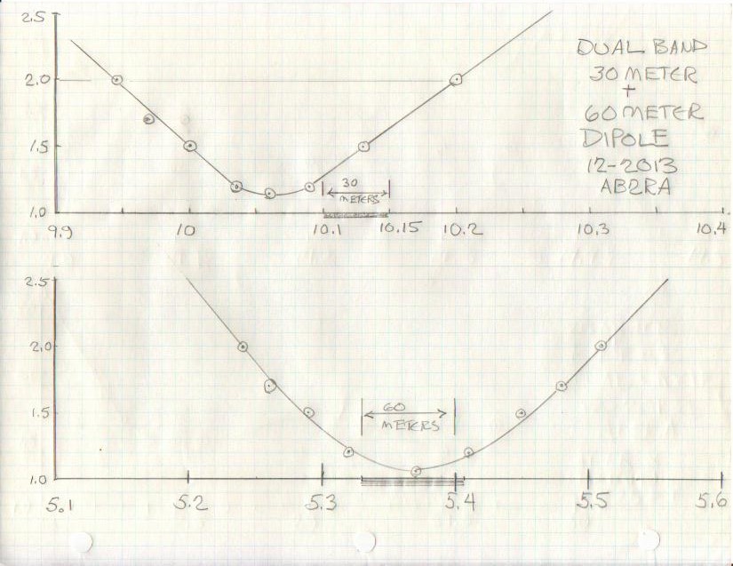
THE 60 AND 30 METER DUAL BAND DIPOLE
The original Jetstream Multiband 80 - 10 Dipole never had coverage of these bands. I put up another separate dual band antenna for the new bands, now that I had a rig (FT-950) that covered them. See Figure 8 for the SWR curves.
WHAT ABOUT 17 AND 6 METERS?
I think you can do this if you optimize the 6 meter performance as a 3/2 wave and take what you get for SWR on 17 meters. I saw something on the web that did this OK. I put up separate dipoles for these bands, since they are small and inexpensive. The percentage bandwidth on 6 meters is 8%, which is pretty wide, if you plan to use CW, SSB and FM. It is nearly as big a challenge as 80 Meters, so I decided to keep it simple. I may try a bowtie style design on 6 Meters or maybe a bowtie on 17 Meters and see if the 6 Meter 3/2 wave harmonic is similarly wide band. If you give it a try and it works, let me know.
UPDATE 6/10/2015
This addtional information is in response to an e-mail query about this page.
Wireman is about the same price for center insulator as the inferior ones.
All stainless hardware, drip ring, better braid to attach, workmanship excellent.
Ductseal from local electrician supply (brick about $5 for lifetime supply) seals coax connector and is easily removable.
Cheaper than the sealing wrap that is the exact same material.
PVC pipe will work fine.
I buy the pipe caps to keep the hornets from making nests in them.
Also keeps water out so doesn't de tune.
I drill a small hole in the bottom to drain water which may enter as it travels on the wire thru the spreaders.
You can buy a long piece of PVC and cut it into the various lengths with a sharp hacksaw. Deburr it so the end caps can be removed if necessary.
I recommend 4 ft at the ends if you can manage for between the 80/40. The wider spread, the less interaction and more bandwidth.
Then at the 40/20 half that length (2 ft spreader) and the 20/10 will be 1 ft.
Make some intermediate spreaders or it will tangle in the wind.
PVC is very light, but might consider #12 ga wire for strength.
One other approach if you have room is to do the broadband dipole on 80/75 with separate wires to separate trees about 20 ft or more apart. Better SWR curve on 80 and maybe helps 40 too.
Then do just a 40/20/10 with the multiband in the middle of the two branches of the 80/75.
One center pulley and coax for all of it.
If you want a multiband antenna for cheap (don't have to buy a tuner and GOOD open wire aint cheap) that will match or be better than the conventional G5RV this is the bees knees. Easier on your radio too.
Jetstream kit does not space antennas a far apart; only 6 inches. Same deal for the Alpha Delta.
Lots of interaction between various bands.
Still gonna need a tuner at the band edges unless you cut it for phone or CW and only do one mode.
I use two separate end ropes to the same tree on my installation on Long Island from the 80 and 40 antennas.
I put the 20 and 10 on the INNER part of the spreaders to keep them tensioned.
That way nothing flops in the wind.
This method went thru Sandy without a scratch.
I wind a 6" of bare stranded wire around each antenna wire as it passes thru the spreader to keep it from sawing back and forth in the wind and keep the 20 and 10 meters from losing tension due to slipping toward the center gradually.
Drill as small a hole as possible for the wires in the spreaders to keep rain and bugs out.
Lay out all the wire on the lawn near the final location and feed the spreaders onto the wire toward the center, then wrap the anchor wires on the spreaders. Rewrap the 6 " anchor wires tightly once you get it all tuned.
15 meters is a "bonus band" that will require a tuner. The length of the 50Ω coax may help or hinder a match. Try inserting a short length jumper (3 ft) to see if the rig's built in tuner will match. The 3/2 wave 15 meter antenna (really the 40 meter dipole) has significant gain and is about 150Ω resistive depending on height. It is essentially a coax fed G5RV scaled for best performance on 15 meters.
For how to build information, construction details and material sources for this project, see my article:
Building Dipole or Wire Antennas.
INEXPENSIVE SIX METER DIPOLE OR DUAL BAND 6 AND 10 METER DIPOLE. Updated 7/18/2017
Build your own inexpensive 6 meter dipole. This antenna would be good for a new Tech licensee to get started on 6 and 10 meters. This is a casual use of my station. I never had a good location at the top of a hill and a rig that covered six before. I did this just to get on the air on six to see what it is all about.
A commercial vertical will cost you $100 and up. A horizontal small 6 meter beam will cost even more. This does not even get into the cost of the support pole or tower, and anchoring it to the house. Then you need a rotor, more money. It is so inconspicuous that it will pass even the pickiest of XYLs or HOAs. It will fit in an attic. It can be built dual band ten and six meter style, as described above, since that is an approximate two to one frequency ratio.
This dipole can be installed either vertically hung from a tree branch or horizontally as shown. Bring the coax away from the antenna at right angles. NO BALUN IS NEEDED!! I use a Budwig insulator because it has very short leads. I do not use the CQ-801 center insulator because the braid adds significant length, and can move around and change resonance on this band; that is not a factor on the HF bands of 10 meters and below. I use the WW2 surplus "egg" ceramic end insulators, installed backwards, to get a very short loop in the end of the antenna wire to get accurate resonance. I do not know if the cheap nylon plastic ones have loss on 6 meters, but the durability of them is a proven liability. See the photos elsewhere on this page. I use bare wire, since it cuts to formula length and is easy to adjust for resonance. A brass pulley is used to raise and lower it from the tree support. I use standard "duct seal" from LOWES in a brick to seal the coax connector. Inside the connector, there is dielectric compound to block out water and further seal it up. Use good TEFLON connectors and good quality coax, not RG-58/U for 6 meters to prevent loss.
SWR is less than 1.3 to 1 over 50 to 53 MHz. Do not bother to adjust the upper 53 to 54 MHz for SWR, since that is used only for RECEIVE on the repeaters. The SWR is not bad there either, but optimize the transmit SWR as stated, centered on 51.5 MHz to keep the transceiver happy.
A dipole is about 1.5 S units below a small 3 element beam. Each additional properly spaced director element after the first 3 elements only adds about 1 dB more per director element, while increasing the mechanical complexity. This 6 meter dipole is high enough off the ground and away from other structures to be an effective low angle radiator. When the band is open, even QRP signals achieve surprising results; that is why they call it the magic band. This dipole hits the local repeaters, even though it is horizontally polarized. You could hang it vertically. To work simplex FM, AM or SSB/CW, my primary interest on six, horizontal polarized is the best way to go for me. For better work to mobiles and repeaters, mount this dipole vertically. In the 50s and 60s, there were no repeaters on 6, so everyone used an omnidirectional horizontally polarized "halo" for mobile, which is quite similar to the new "cobweb" dipole antenna from MFJ for HF. This dipole has a wide enough pattern that if it is installed so that Northeast and Southwest is broadside to the dipole wire, a rotor is not needed to make contacts in the most likely directions. Get on the air inexpensively this way. If you get hooked on 6 meters, you can always go to a bigger antenna later.
NOTE: Do NOT try to add 6 meters to the multiband HF dipole. It will be difficult to get to resonance, will not have good band width, and you can make a much more efficient 6 meter dipole as a stand alone. The same is true of 10 meters; as frequency goes up, multibanding gets more quirky, and SWR curves and efficiency suffer. These antennas are small enough that they can demand their own space and feed line.
|