Gert, PA3CRC has graciously provided hi-res scans of the HQ-170 manual and schematic. Thank you, Gert! ^_^
Click on the items below to view/download.
Notice: Please read the Notice and Terms of Use page regarding these and all downloadables.
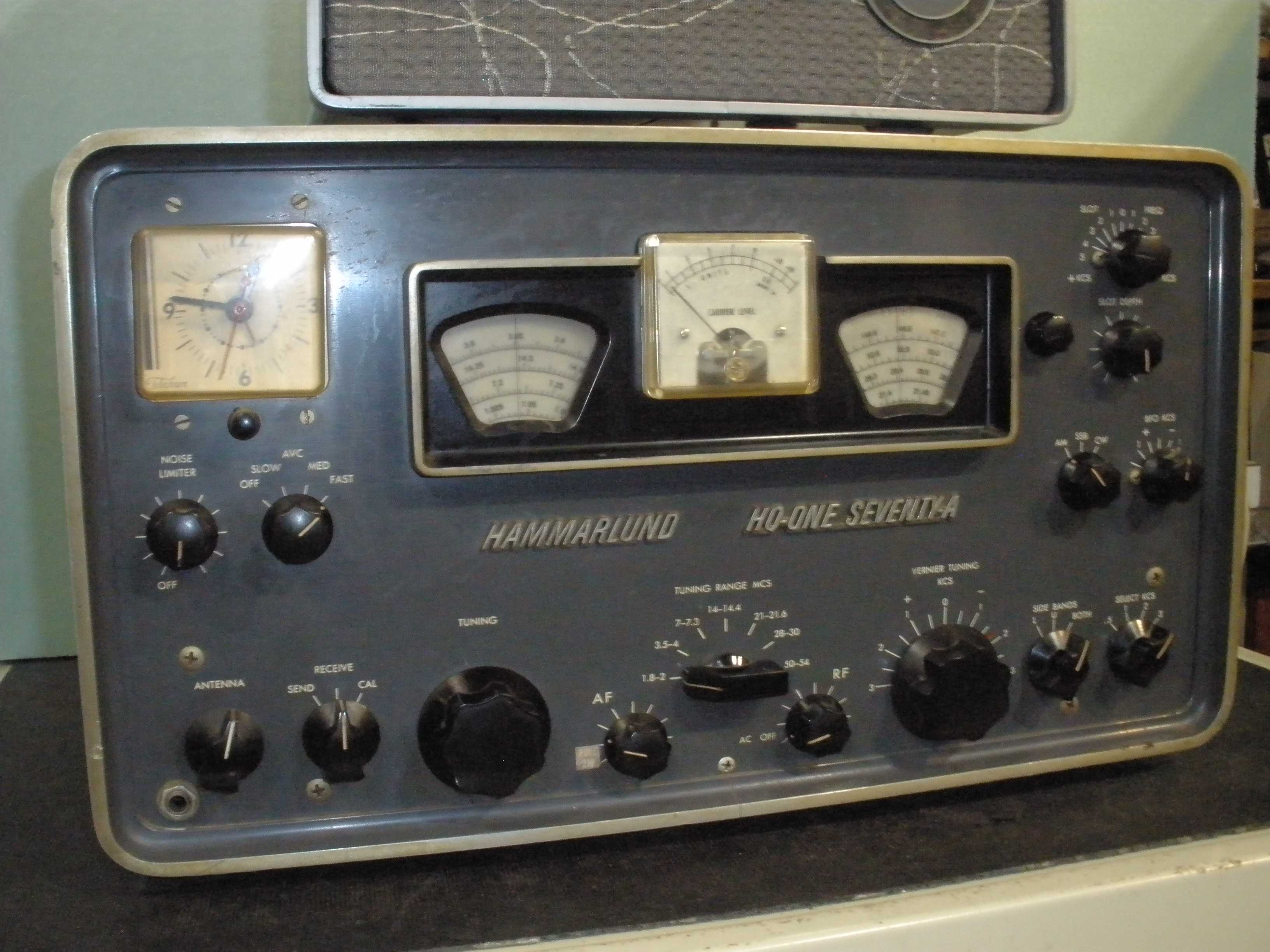
 The manual (14,658k pdf)  Schematic - Left page Schematic - Right page Simply put, the HQ-170 is a ham band only 160 through 6 Meter receiver. It does not cover the newer WARC bands of 60, 30, 17, and 12 Meters. The HQ-180 is general coverage 550 KHz to 30 MHz, ALL HF ham bands (including WARC) and shortwave in between. But the HQ-180 is more complex in subtle ways such as the inclusion of a crystal filter at the higher IF of 3.035 MHz; this makes the ultimate rejection of stations outside the normal passband of the low IF of 60 KHz superior to the HQ-170. Also, there is an extra tube, a 6BA6, in the HQ-180, which may confer a bit better overload tolerance, at least when that "gate" tube is active. In addition, the individual oscillator coil cans in the HQ-180 seem to be better quality, and are easier to adjust, since they have metal screws driving the ferrite slug (and are therefore much less likely to jam). The HQ-170 has two bands per coil assembly, and they do not appear to be as good a quality (paper coil forms instead of ceramic), possibly making for more drift. When adjusting them, to get to the bottom coil, you must insert the tuning tool through the top coil, disturbing the adjustment. You can get around that by rearranging the order of alignment, so the top coil (and it associated band) is done last. But the oscillator coil adjustment in the HQ-170 is decidely "jumpy" especially on the upper bands. I find it better to make the final oscillator to dial calibration tracking with the trimmer capacitor LAST. The 180 is easier to adjust, not so jumpy, and has better stability. It covers the WARC bands and WWV too.
The "A" version has a lid that opens in the top, to change the 6C4 and 6BE6s that fail often if you do not disable the "keep alive" feature. The "A" version has a third (center) position on the mode switch, adding "SSB", which is a fixed (center of the IF) BFO frequency instead of adjustable. In the original version 170 and 180, the product detector and all the nice stuff still works when the mode switch is set to "CW", but you have to set the BFO to the right frequency on the selectivity curve. The rectifier in the "A" is solid state, instead of a 5U4. In the "A" version, the filaments of the 6C4 HF oscillator and some of the 6BE6s is on all the time, not controlled by the power switch; this is claimed to reduce drift. It also results in much shorter lifetime of those tubes. Therefore I recommend plugging the receiver into a power outlet strip with a switch that disconnects the AC power when not in use. There is a "system socket" in the 170 for various accessories. For instance, you might want to add an FM detector. There is an HQ-170-VHF model that includes a 2 Meter converter inside the radio, with a calibrated dial for that band. The VHF version 2 meter converter also served as a preamp on 6 meters. This 2 meter converter was sometimes field installed by the owner, and the craftsmanship could be an issue. Note that the power transformer in the earlier versions was a -1 and the factory VHF versions was a -3, even in the 115 VAC models, because more current was needed for the VHF converter. There was a HQ-180AX version that had 11 crystal controlled channels in addition to the normal VFO tuning. Also, the "A" version antenna trimmer capacitor was moved to the front panel and connected by a length of coax, which eliminated the dial cord and pulleys of the original version. This unfortunately resulted in intractable VHF parasitic oscillations on the 6 Meter band of the HQ-170, and sometimes the 10 meter band on both the HQ-170 and the HQ-180. Very late versions had a plug for the AC line voltage selection. There could also be a plug for the clock accessory, which was sometimes field installed. Of course, there were 60 cycle clocks for USA and 50 cycle clocks for export, and the clocks were 115 VAC and had to be wired so that they worked on 220 VAC, turning anything to do with the AC wiring or power switch into a nightmare. Of course, the keep alive transformer for the 6C4 HF oscillator filaments was included in that rats nest. Get a true version of the exact schematic for YOUR particular flavor of HQ-170 or HQ-180, or do not mess with this part of the radio. The easiest short cut to defeat the "always on filaments" feature is to find the AC input to the main transformer and connect both leads of the smaller keep alive filament transformer there. If your radio has provisions for 115V/230V, do not do it this way; you have to trace out the wiring with a schematic. Another difference between the 170 and 170A is the main tuning capacitor has only two sections instead of three in the A version; the antenna trimmer on the front panel has to do more of the work. The muting during transmit is different between the HQ-170 and HQ-170A. The original 170 has an AC line type socket on the rear; the A version has those external mute connections on the 8 pin socket, and the AC line type socket is missing. Some of the 180s had metal boxes over the tuning capacitors, to keep out dust.
There was a very effective accessory Noise Blanker or Lamb IF Noise Silencer available for the 180. I am not sure if it was intended for the 170, but it surely could be adapted to that use. It bolted on top of the right hand tuning capacitor as viewed from the front in the 180. An extra red knob appeared on the noise limiter control on the front panel left hand side. I will post a link to the schematic. I may even attempt to build one and document it here.
Lastly, this was the pinnacle of the technology for that day, the dawn of SSB and the end of AM as a dominant mode. Collins introduced the crystal controlled first HF oscillator, followed by a highly stable PTO linear master oscillator that operated on the same frequency for all bands. Stability and dial accuracy took a huge leap forward by orders of magnitude. Also, people were demanding transceive; zero beating the transmitter and keeping it on channel was such an essential function that the ability to work "split" frequency was not included in early transceivers. Backward compatibility to older drifty equipment, often in a multi station "net" environment then required a Receiver Incremental Tuning (RIT) control, a field modification that shows up on early transceivers like the Heath SB-100. Lattice crystal filters and mechanical filters replaced the finicky and hard to adjust low frequency IF filters, and provided reliable selectivity without complicated alignment procedures with equipment too expensive for the average ham. Soon, other manufacturers like Drake and Swan followed suit. Hammarlund did not keep in step with those changes, and soon disappeared from the high end market, and eventually from business in the end. Hallicrafters (SX-100 and others) used a simpler low IF system that switched second converter crystals, one for either sideband; it worked better than the complicated Hammarlund system used in the HQ-170 and HQ-180, and it was a lot easier for the user to align. The NC-303 system works better and is easier to align than the Hammarlund as well. But these are great radios, and the impressive size and the level of technology for the time continue to gather a enthusiastic group of loyal aficianados. Count me as one of them. I now have a National NC-303, and its superior quality in the HF oscillator components puts it ahead of the HQ-170 in stability. It does not need a "fine tuning" knob; the main tuning dial, with its mechanical vernier, works fine on all bands even for CW and SSB. The NC-303 had accessory converters for 6, 2, and even 1.25 meters, with an accurate dial read out for them. I use the HQ-180 with the Viking II because of the WARC band coverage.
Sensitivity on all bands of the HQ-170A I work on later in this article is much better than the 1 uV spec on AM, closer to 0.3 uV. But 6 meters needs 150uV for good copy. We knew that, they all do that. And drifty. But this one did not seem to oscillate. You got lucky. 6 meters is on a separate RCA jack. You can replace that with a BNC if you want. I would also suggest an F connector for it. Then you could get a small solid state TV booster amp, A 20 dB TV amp would get you down to around 10 uV, which is useable with a good antenna on a local QSO on 50.4 MC.
If anything, the HQ-170 is a victim of its own success in the RF and IF gain department. Two modifications attempt to address overload conditions in the IF and detector. I evaluate them later in the HQ-170 repair report, and found that they introduced problems that were worse than the one they were trying to solve. It was better to just reduce the RF gain control on the front panel when overload conditions exist. Isn't that why there is an RF gain control on a radio? One other approach would be to install a lower gain tube substituting for the 6BA6 IF tubes; I would suggest 6BJ6 or 6BD6 for starters. In stock form, the HQ-170 I did the repair report on, had much better than 1 uV sensitivity on AM, and more like 0.3 uV on CW, when it was finished. But S9 was around 10 uV. The lower gain tubes might bring that to a more normal 50 uV. But as shipped, these HQ-170s were hot - even better than my beloved NC-303.
NOTE: there is no xtal calibrator on 6 meters; 100 KC is too close a spacing for 6 anyway, and it is hard to implement without compromising HF sensitivity. A 1 MC or a 500 KC calibrator would be more appropriate for 6 meters. They were just trying to deliver this as a "feature" to list for sales.
In the late 50s and early 60s, it was very competitive between these 3 radios:
The NC-300 & 303 used separate crystal controlled converters for 6, 2, and 1.25; much more realistic, but much more expensive. The SX-101 did not provide for 6 or 2 meters at all; it also only had two 50 KC if cans. The stability on 15 & 10 was better for the NC-303 and the Hallicrafters SX-101 than the HQ-170. By comparison, the HQ-170 has six tuned circuits at 60 KC (equivalent of 3 IF cans), for more skirt selectivity than the SX-101. The NC-303 also has six low IF tuned circuits (equivalent of 3 IF cans), so both are better than the SX-101 on selectivity. The guy who brought me a SX-101 to work on was in a big hurry, so I did not have time to play with it the way I wanted to; the SX-101 had a lot of spurious responses. I speculate that a shield was missing from over the front end circuits to keep the IF from radiating back into the front end. It may have also mounted the heater that kept the drift down (which was a much better system than sacrificing tube life like the HQ-170 & HQ-180 did). Worse yet, the SSB/CW detector did not work right on the AVC; the S meter read about 1/3 scale in SSB mode. Read the manual for the lame discussion. Plus there are a lot of "bumblebee" or black beauty capacitors to replace:
http://www.k3msb.com/sx101a/subconverter/writeup.html
One reviewer notes the same audio distortion on AM in the SX-101, HQ-170, and NC-303. He attributes this to inadequate filtering to remove audio from the AGC. NOTE: You MUST use the exact tube called for in the manual for the audio output in the SX-101, no substitutions, or you will get distortion. The reviewer does not mention the spurious responses; maybe his test unit had the shield installed over the front end.
The SX-101 used a resistive heater to get stability without keeping the filaments lit, a much better idea for tube life. I disable the "always on" feature of the HQ-170; the clock can power it up ahead of net time, if I need that.
The use of more than 100% positive peaks on modulation of transmitting stations leads to distortion when receiving on a vintage receiver. In all the reports on the SX-101, HQ-170, and NC-303, distortion increases as 100% is approached, due to the square law detectors involved. That is why I do NOT use 120% or more positive peaks in my AM transmitting equipment. An external synchronous detector will fix this and reduce multiple types of distortion. But if there is a drifty DX-100 in the roundtable, the synchronous detector will lose its mind when they sign in off frequency. Keep these points in mind when evaluating this vintage of receiver. In modern transceivers, even the low to middle price range radios which are essentially a SDR (software defined radio) with a front panel, the synchronous detector is not included, and distortion will occur on 120+% modulation peaks.
Bottom line: the HQ-170 has a much hotter sensitivity than its competitors. And very good selectivity, when it is working right. Not so good on the stability on 15 & 10. The SX-101 was not so good on the IF selectivity and had spurious responses. The NC-303 was a better over all performer, no spurs, decent selectivity, excellent selectivity, great band spread tuning, adequate sensitivity for the noise floor most of us have to deal with these days. That is why it is my go-to AM receiver at this time.
W1VD tests the NC-303 here:
http://www.w1vd.com/NationalNC-303.html.
No big complaints other than the AGC time constant too short.
HQ-170 user reviews:
http://www.eham.net/reviews/detail/3807.
Read the K7PP reviews (he has videos of working on the HQ's) and KE4EZ, who likes it for AM on 75 at night. I still like the 170 and 180 in my shack for the same reasons.
The HQ-180 is more stable for 20 meters and up than the HQ-170 owing to better components in the front end. Plus it has a crystal filter at the 3.035 MC first IF, for better skirt selectivity, and possibly better for close in signal intermodulation resistance. Also there is an extra 6BA6 gate tube that may make the AGC perform better under overload conditions.
This test result by W1VD on the 170 rates it pretty good.
http://www.w1vd.com/HammarlundHQ-170A.html.
The only receiver that I would stack up against these 3 and prefer is the Drake 2B. That was an amazing piece of engineering that got stability, selectivity, sensitivity right for a much lower price and smaller package. It was also one of the first affordable receivers to use a crystal controlled first oscillator, which put it way ahead of the Hammarlund HQ-170, National NC-303, and Hallicrafters SX-101. The era of free running HF first conversion oscillators and AM was officially over.
Drake 2B tests:
http://www.w1vd.com/Drake2-B.html.
If you have the HQ-170A version, the 6 meter band will likely have spurious responses when the antenna trimmer is tuned, and they appear at multiple points on the band. This is a parasitic oscillation due to the long length of coax from the antenna coil to the trimmer on the front panel, and removal of some sheet metal shielding. The NON-A version had a capacitor right at the antenna coil, with a dial cord mechanism so the knob on the front panel could drive it, and was better about this problem. I never try to get 6 meters to work on these, since it is deaf as a post and too drifty as well. A good 6 meter converter is much better. Sometimes this glitch can appear on 10 meters, and lead dress or a low ohm resistor in the plate or grid lead for that band only can help. The NC-300 and NC-303 did not try to "stretch" the performance of a 6BE6 mixer and a free running LC oscillator beyond their ability, so a separate 6 meter converter was provided, at more cost.
Also, if you have an A version, rewire the primary of the small filament transformer that keeps the 6C4 and 6BE6s hot. This was to improve initial drift. But it ate tubes up in a year. Or you can use a line outlet with a switch to avoid rewiring. The AC wiring due to the clock, and sometimes the provision of 220 AC operation can make you crazy. Get a manual which exactly matches your radio from W7FG.com if you attempt this on a 115/220 receiver.
The 170s and 180s could have hum on only the upper bands. This was due to FM from the 6C4 filament. One fix is to DC operate the filaments. You can easily use DC on all the small tubes driven from the small "keep alive" filament transformer used in the "A" versions by providing a solid state rectifier, filtering, and possibly a three terminal regulator. Hammarlund suggested selecting the 6C4 from a box of tubes by trial and error.
Hammarlund HQ-170 and HQ-180 receivers normally have some hum with the volume turned all the way down. The first input filter capacitor is not quite big enough to get rid of all of it. Some people go up to 100 uF for the input section, but this is asking for a lot of the solid state rectifiers in the A version. There are resistors not shown on the schematic installed between the solid state diodes and the first filter can section. Check the photos on Woody's web site (link to his excellent detailed photos below), you will see it there. I added some in my work on this HQ-170. Coincidentally, they are nearly the same value, except I used separate resistors for each diode. I would not recommend putting a 100 uF capacitor directly on the output of a 5U4 either; read the RCA tube manual, it makes recommendations for maximum input capacitance of a capacitor input filter. It is better to live with it. On the other hand, hum when the volume is turned up can come from sloppy wiring on a field installed clock (near the low level stages). Also, if the Phillips screw is loose on the lower part of the front panel (holds the "auto response" terminal strip), bad grounding can result. Hum can also result from H-K leakage in the 6BV8 or 6AL5. Missing or lose tube shields on the audio or detector or noise clipper stages should be replaced.
The fast tuning rate on 10 meters is normal. The tuning on 10 meters has to cover about 2 MC. This is even more evident on 6 meters, which is 4 MHz wide. That is why on both the HQ-170 and HQ-180 there is a vernier tuning knob, which acts as a tuneable first IF frequency. On the other bands like 40, it only has to swing 300 KC. By the way, it is normal for drift on 40 to take 7295 off the end of the dial on some 170s. Just misalign it a bit, if you have to. Getting the drift down on that point is a big job. The other bands do not seem to have this problem.
The chirpy signal on CW receive is partly due to the AGC being applied to the 6BE6 that changes from 455 to 60 KC. It pulls the oscillator on strong signals. Disconnect the AGC from that and ground it thru an appropriate resistor as if using NO AGC. Also, another voltage regulator is added for the 150 volt line. I tried the AGC part of this and it did seem to help. But the operation of the S meter seemed odd, and removing the AGC seemed to allow overload on strong AM signals. AM is the primary mode this receiver. For NO modifications, with strong signals on CW or SSB, just turn down the RF gain. I tried another similar modification that applied AGC to the last 60 KHz IF stage, and it caused distortion on very strong AM signals. This seems counter intuitive, but that is the way it worked for me. Hammarlund knew what they were doing, it seems.
http://www.w8ji.com/hammarlund.htm
The CW AGC initial DIT response and slight delay in AGC action on the first sound of SSB on strong signals can be annoying. Use slow AGC for CW and SSB and/or reduce the RF gain to compensate. If you analyze the schematic or poke around with a voltmeter you will find the last 6BA6, in the 60 KC IF has no AGC. I tried another mod I found out there that added AGC to that tube. It seemed to increase distortion on very strong AM signals, as noted above. I did not use this one either.
The HQ-170 & HQ-180 both have inadequate filtering to keep the audio out of the AGC. You can see the S meter jumping with modulation on an AM signal. The triode used to drive the meter is a specialized VTVM, and it responds to the changes in AGC voltage. Any tampering with the AGC system must take this into account and requires a lot of sophisticated equipment. Read the W1VD reviews of all the receivers of this period; they all experience some of this problem. I found both of these AGC mods may have improved CW/SSB performance marginally, but the AM audio distortion on strong signals got worse, just as W1VD described. The HQ-170 and HQ-180 both have an RF gain control. Use it. There is a lot of gain in the RF and IF sections of these receivers. So much so that with a good set of tubes and careful alignment, a 10 uV signal often is S9, if the controls on the back are adjusted for full scale deflection with maximum signal. It is better to adjust it that way and set the RF gain to provide a realistic S9 signal level. That way, when the AGC goes to its maximum saturation voltage, no distortion results.
If you have BC band stations appearing on 160 Meters and are using a very large antenna, here is a tip. Remove all the balanced input wiring, and ground one side of the input coils on all bands. This move will contribute to RF stage stability on the upper bands on either a 170 or 180. Use RG174 to get from the coax antenna connector to all the HF bands. Use a separate BNC for the 6 meter RCA jack, and use only coax for that input coil as well. On 160, use a bridge or L meter to measure the input coil for that band after you have it aligned (about 6.8 uH). Insert a (1000 to 900 pF) mica capacitor in series with only the 160 antenna coil, that broadly resonates with that inductance. This inserts a series resonant circuit, giving a little more selectivity on 160. I have not seen this on any other bands, and it only happens when you are close to a BC transmitter, using a large antenna like the full wave loop which I have. (Make sure you are not hearing harmonics of the BC station by checking the point it appears on the band.) If you are using a link coupled transmatch, you may not have to worry about this, because the extra tuned circuit reduces the BC station amplitude before it gets into the receiver. I also find that the range of the tuning slug and antenna trimmer on 160 only in 170A versions is not sufficient to get to resonance. I add a small fixed capacitor (20 pF or so) in parallel with the secondary of the 160 antenna coil if necessary to get to resonance, and the trimmer now is able to tune the whole band. In the A version, this is probably due to the removal of the third section (RF input tuning) of the main tuning capacitor. The two remaining sections are for mixer and oscillator, possibly to keep the price down. If the antenna trimmer is at its maximum or minimum on one end of the band, and the slug in the coil cannot bring it to resonance, try this tip on 160 meters only.
There are a number of Hammarlund acknowledged symptoms in this service bulletin: http://www.hammarlund.info/hq178svc.pdf.
The so called "auto response" on Hammarlund receivers is a disadvantage. Even the sharply selective HQ-170 and HQ-180 can be helped by audio modifications. The author of the article below does not think these receivers are worth consideration for AM operators. I would disagree, since the bands get crowded at night; the HQ-180 is a big step up from the HQ-145 that I write about on this web page. I use about 2.2 meg or 1 meg in series with a 0.01 uF capacitor from the 6AQ5 plate to the 6AV6 plate in the HQ-170A to bring down distortion after removing the auto response resistors. These resistors are found near the L bracket to the front panel which holds on the cabinet from the bottom screw.
Another approach for more AM band width would be to add a second AM detector after the 455 KHz IF and before the narrow 60 KHz IF, and route it to the audio amplifier, allowing a HI-FI mode. Here are the common mods for fixing that Hammarlund audio:
http://www.amwindow.org/tech/htm/hqaudiomods.htm
Here is a web page that does some performance testing on vintage receivers:
http://www.w1vd.com/HammarlundHQ-170A.html.
The low frequency IF is tricky to work on. Here is a good write up:
https://www.w8ji.com/selectivity_hallicrafters.htm.
Woody is a collector that posts a lot of useful photos of the internals of pristine examples of various equipment. For comparison of a unit that you are repairing, they are essential. See:
When you have time to watch them, they are long videos, K7PP has some amazing tutorials on repair and alignment on YouTube. Google them and take notes!
There was a compendium of all the tricks for the HQ-180 published by a regular contributor to Electric Radio Magazine, Ray Osterwald, N0DMS that you should definitely obtain, if you wish to do a complete refurbishment and improvement of your HQ-180. The HQ-170 circuitry is very similar, so the tips usually are helpful for both receivers. The articles you need are:
- Electric Radio #278 July 2012 begins page 18 Hammarlund HQ-180 A Vintage Product Review Part 1
- Electric Radio #279 August 2012 begins page 20 Hammarlund HQ-180 A Vintage Product Review Part 2
- Electric Radio #281 October 2012 begins page 24 Hammarlund HQ-180 A Vintage Product Review Part 3
- Electric Radio #284 January 2013 begins page 24 Hammarlund HQ-180A Wrap-Up
- Electric Radio #304 September 2014 begins page 12 Improving AGC for the Hammarlund HQ-180 (WA8SAJ)
Get them from Ray Osterwald of Electric Radio. He probably has articles specific to the HQ-170 too, ask him. Get it all at:
https://www.ermag.com/
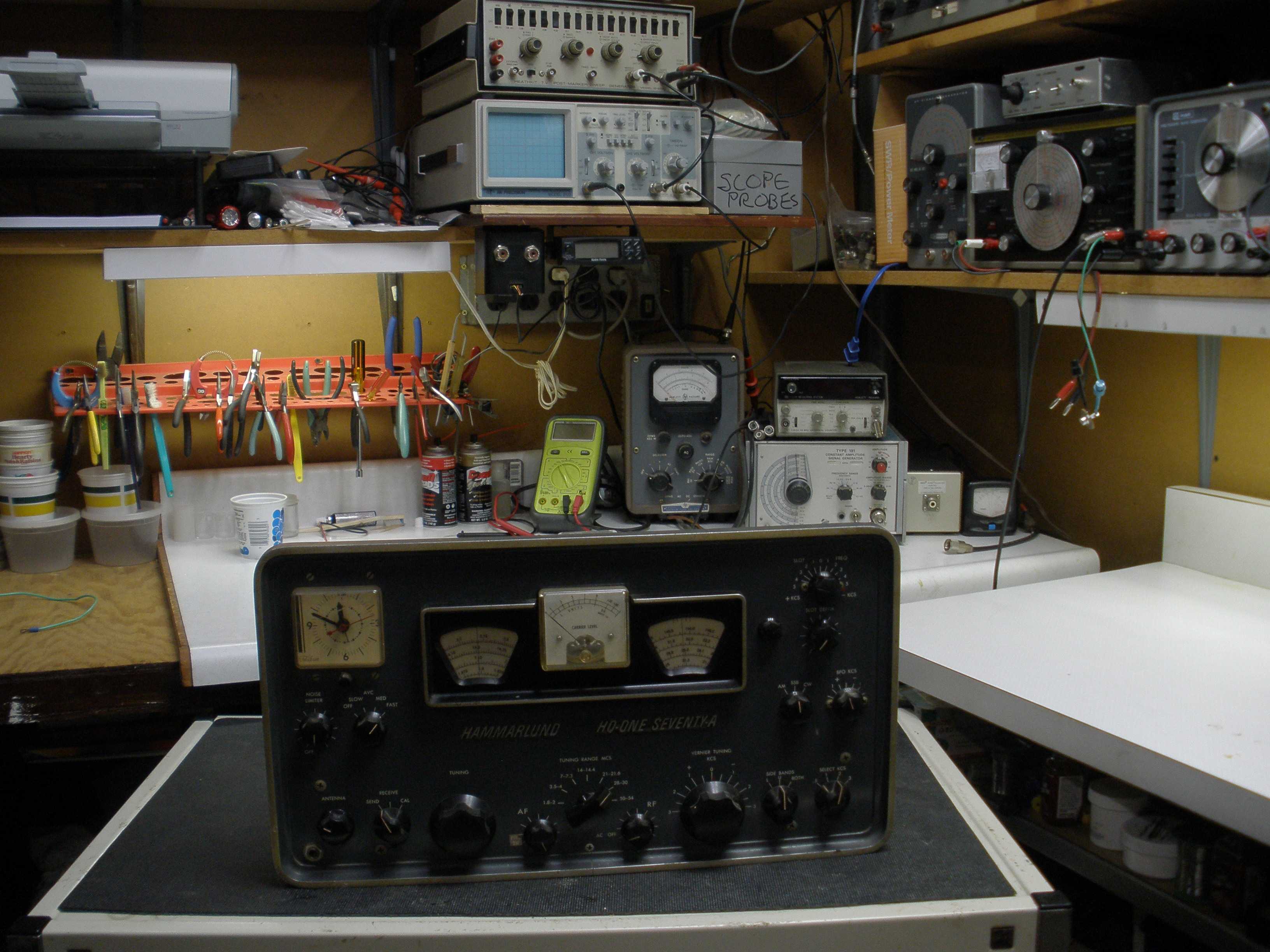
This part of the page will be a photo essay and discussion of the restoration of an HQ-170 as it moves forward. Later, I may add some more about an HQ-180 I will work on. I hope you will find it helpful, if you plan to work on a classic Hammarlund receiver. You may also find it helpful to look at my write up on the HQ-145, since these receivers all share some common design elements.
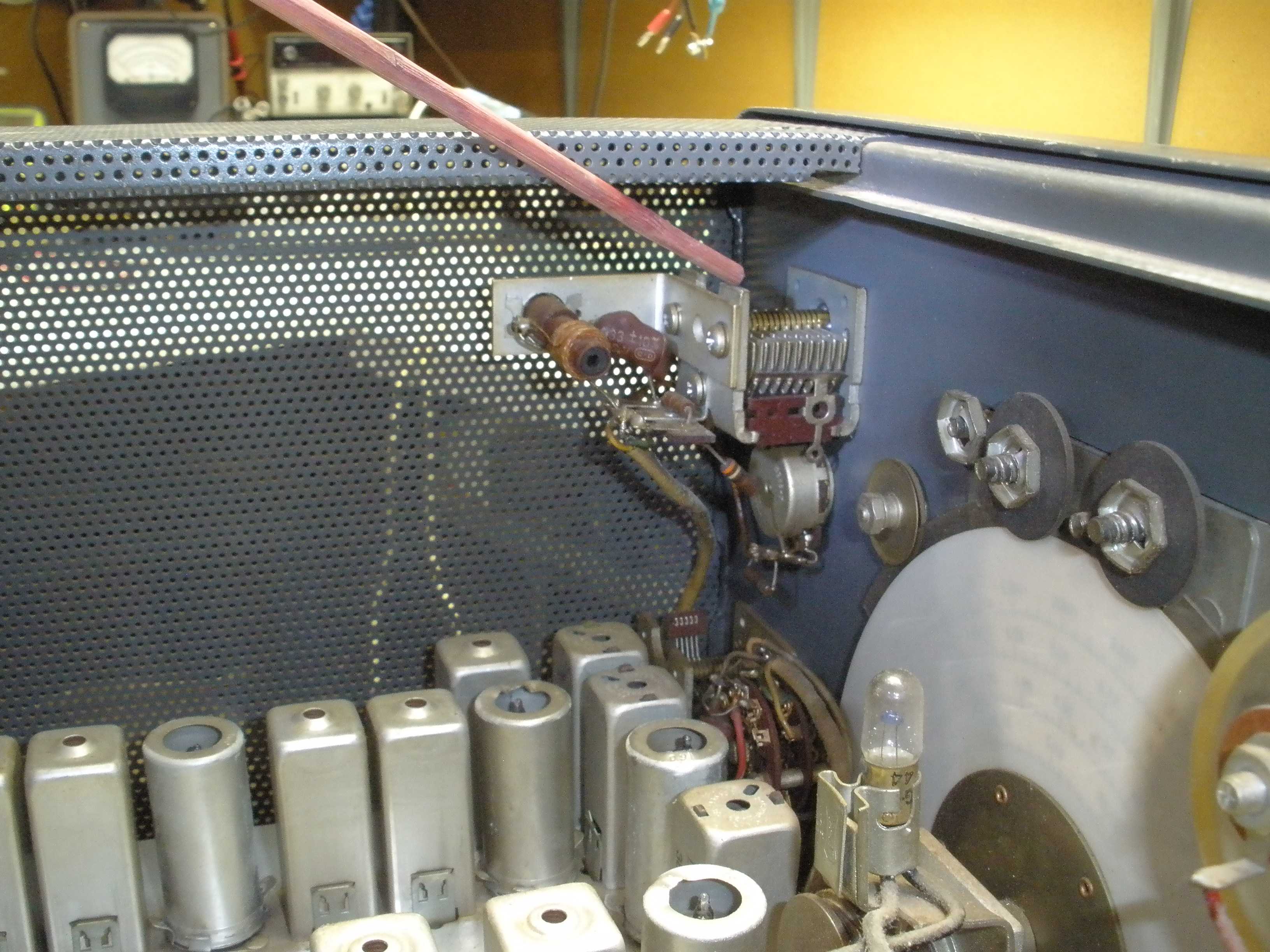
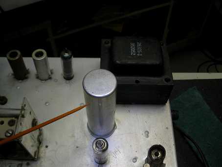
When removing the reciever from the cabinet exercise special care to avoid damaging the Notch Tuning components shown in the photos below. Completely mesh the Notch Frequency capacitor to lower the profile of the plates, so that it does not catch on the cabinet as you slide it forward. Also, the coil can catch on the case and be damaged. Remove the screw in the bottom FIRST. Then with the cabinet upright, remove the 3 screws in the back, and finally loosen (do not remove) the two screws in the top near the front panel. With the cabinet still upright, push the chassis from the back to start it out of the cabinet. Then pull the front panel and chassis straight forward, without lifting, until you have the cabinet successfully separated from the chassis. (When reinstalling the radio back in the cabinet, observe the precautions about the notch tuning, and be sure the L bracket for the bottom cabinet screw goes INSIDE the cabinet.) Now we can get down to work.

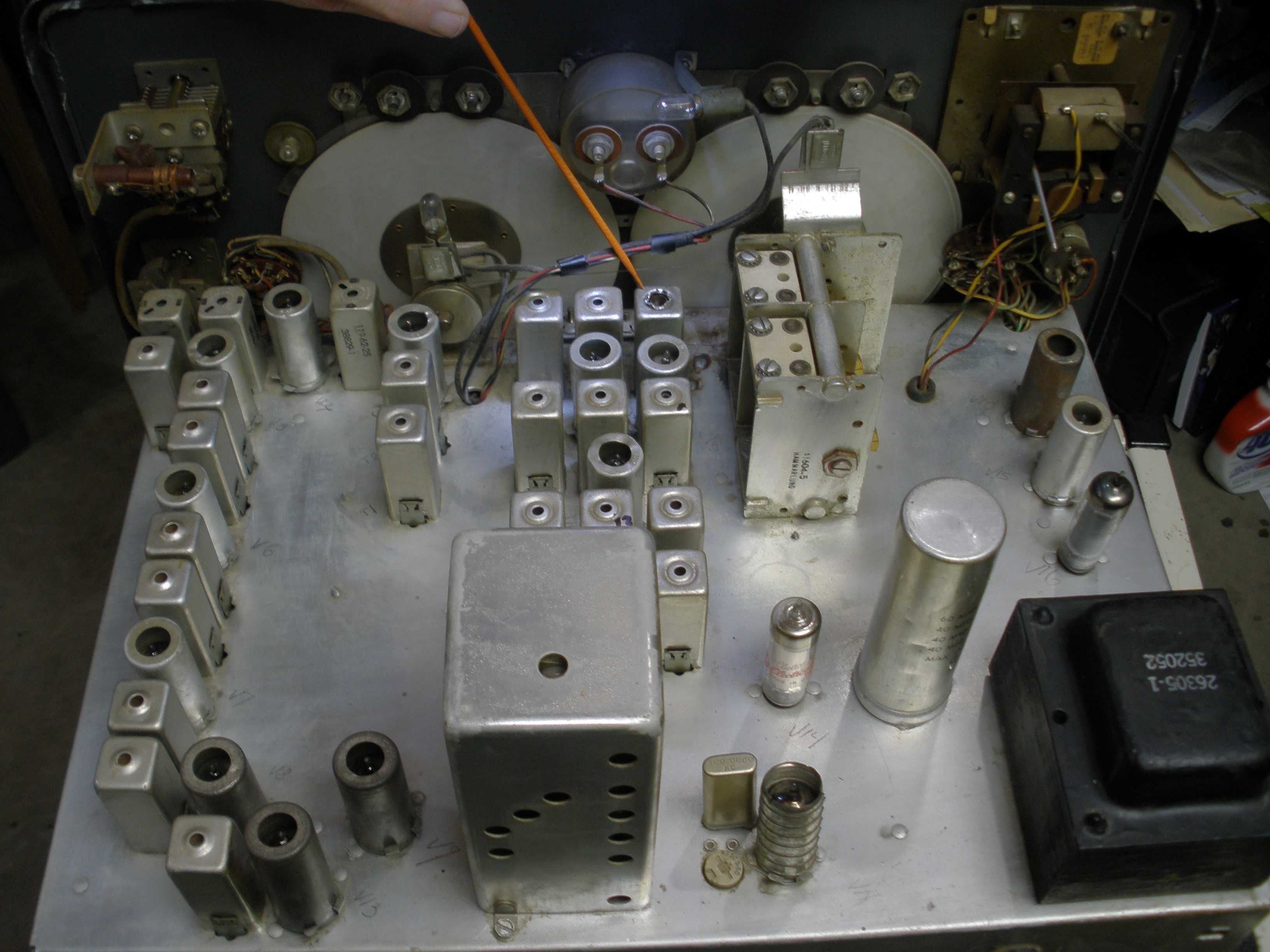
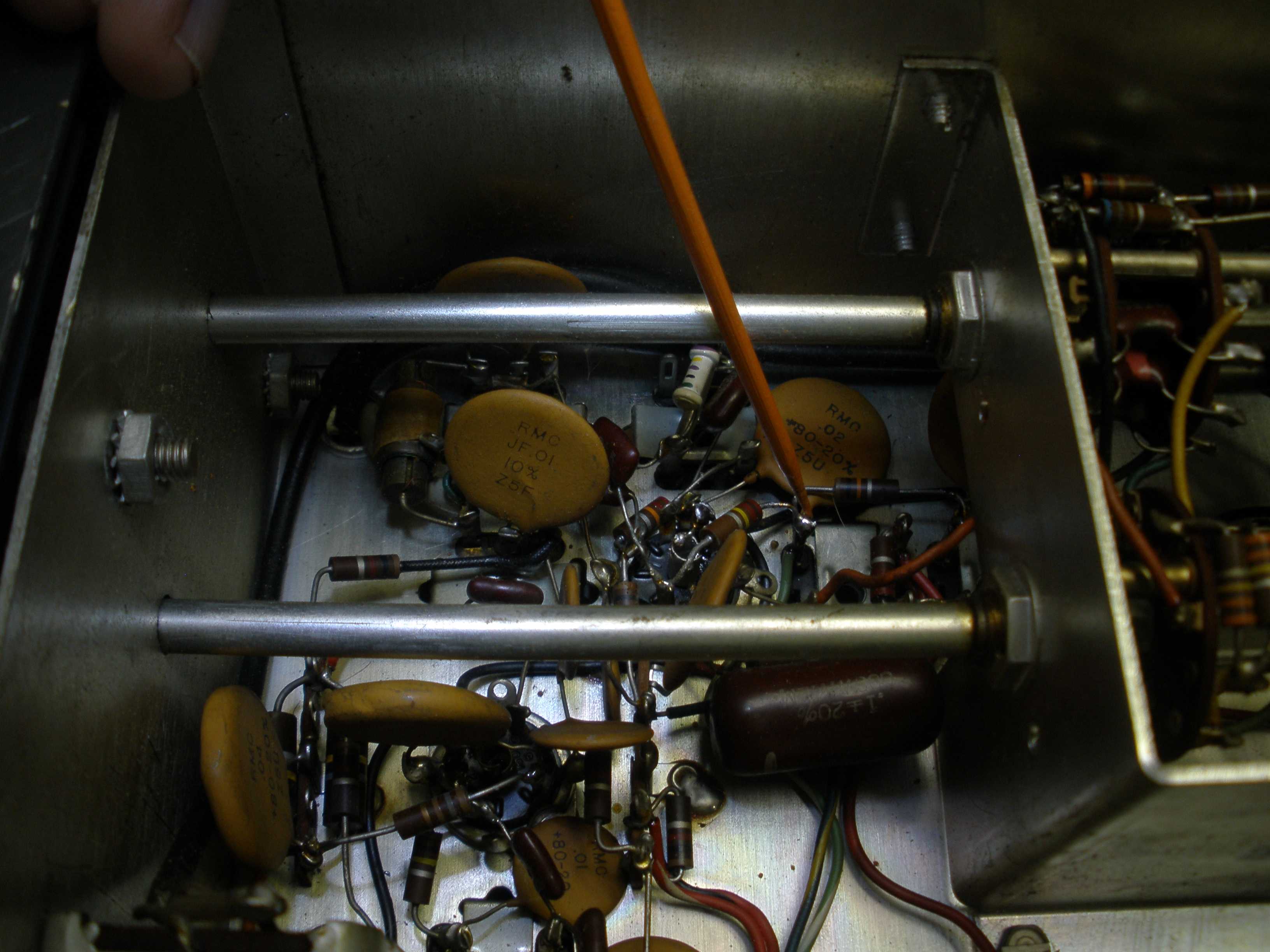
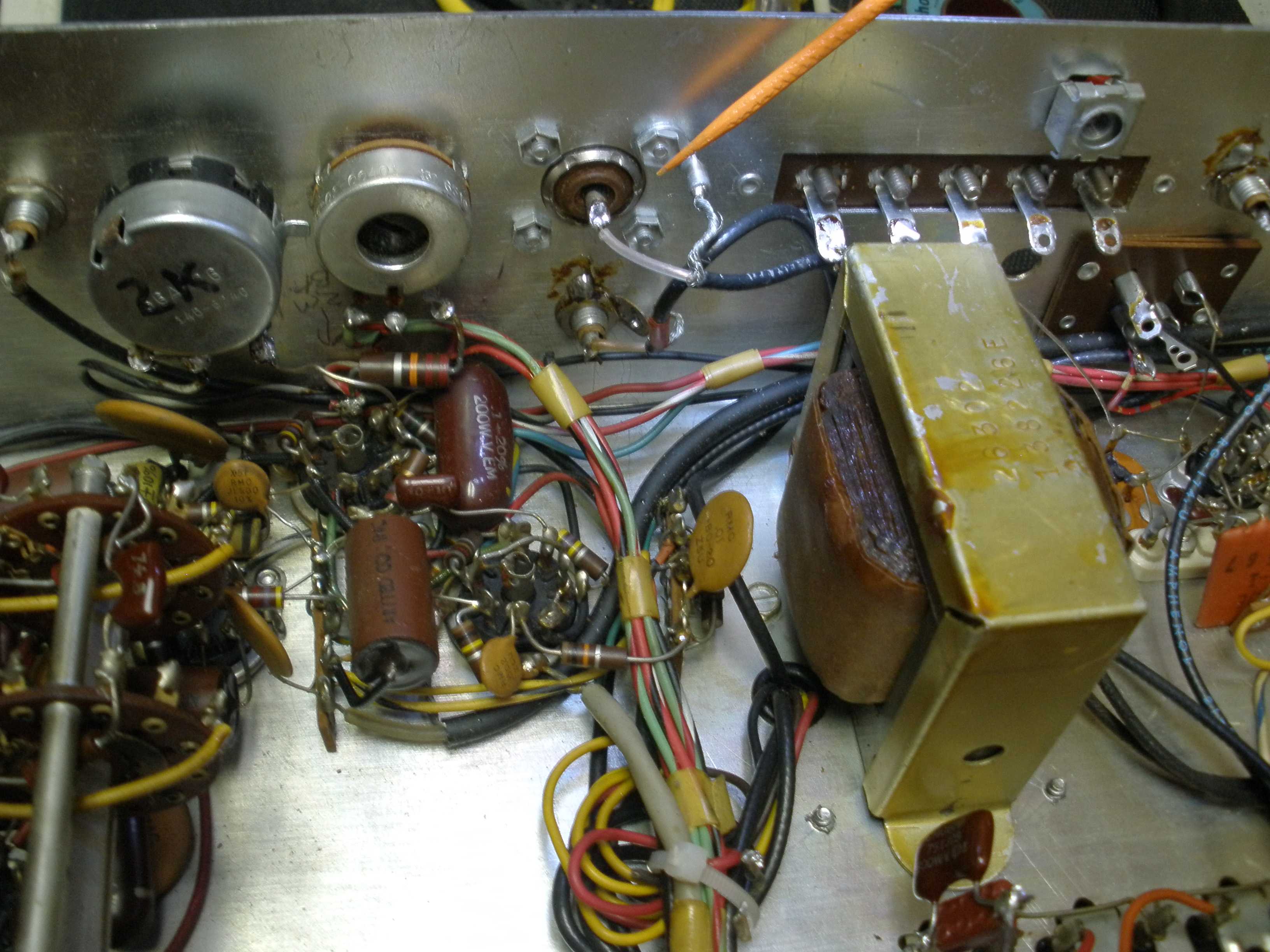
The first step is to visually inspect the underneath of the chassis for burned components, modifications, and crusty white or yellow deposits on the pins of the main filter capacitor can. Also look at the main transformer and filter choke or output transformer for dripping tar or overheating. If the capacitor looks or tests suspicious for leakage or power factor (series resistance), order one NOW from:
https://hayseedhamfest.com/
This supplier manufactures modern electrolytic capacitors that are EXACT replacments for the metal can. There is a video on youtube that shows how to replace it. I differ with his method. Do NOT remove the wires from the original pins of the capacitor. It burns the insulation, and you may wind up with wires that are too short to reach. First, mark the leads with a geometric symbol like the original can: square, triangle, etc. I cut the tabs off flush at the old capacitor base, leaving the wires attached. Then remove the old can, not trying to save it. Clean off the solder from the tabs that were soldered to the chassis and install the new capacitor. Solder the original tabs and wiring to the new tabs, being careful to match the geometric symbol to the correct tab on the new capacitor. Much easier, and no risk of confusing the many red wires to the capacitor.
Use a good capacitor tester that can put operating voltage on it, such as the Sprague TelOhmMike, or one of the Heathkit or Eico testers shown on my test equipment page. A modern digital capacitor checker is useful for testing mica or smaller coupling capacitors for value, but are useless for testing for leakage at the actual operating voltage. If it measure bad, leakage or open/low value, replace it now, if even with a temporary fix tacked in, so that you can decide whether the receiver is worth fixing. Do NOT go hog wild chopping the other coupling capacitors out and changing them at this point. You can make installation wiring mistakes, and introduce new problems, making it impossible to figure out where you went wrong.
Later, you can replace capacitors that look like this:

 Can capacitor If authenticity is not essential, you can install new leaded capacitors below the chassis, on a terminal strip soldered to the old can capacitor pins (bent over and grounded, for support). In the HQ-170 and HQ-180, you may run out of space for this style, and are better off putting in a new exact replacement can. NEVER put new capacitors in parallel with the old can (when it tests open). Generally the open sections that you used for tie points eventually go shorted, and may cause damage later. While you are at it, check the type and value of the fuse. Often previous owners will install fuses with too large a rating, as capacitors start to leak. Install the right value of fuse. Use a 3 amp fast blow on a HQ-170A for 120 VAC operation.
There are a lot of tubes in this receiver. Many are the same type. Test all of the 6BE6s together, then the 6BA6s. Get out your tube tester and go through them and write down the numerical quality shown on your tester. Pay special attention to the 6C4 and all the 6BE6s. The "A" version kept some of the filaments lit when the radio was off. I have seen tubes not even move the needle on the tester. Install the best 6BE6s early in the chain nearest the antenna. The last one that converts the 455 KHz to 60 KHz should be out of the "?" range, but does not play a huge role in the overall gain and noise figure. The same technique applies to the 6BA6s. Heater to cathode leakage is important on the 6BE6s, 6C4, 6AL5, and 6BV8. More on this later. Replace anything that is completely dead, but you can do a receiver functionality evaluation with tubes that are even in the higher end of the "replace" zone. Order any tubes you need now. Do not buy "used" tubes that are not guaranteed, particularly "hamfest" loose tubes not in a box. If you shop at hamfests, inspect the tube to make sure the brand matches that of the box. Not a sure bet, but it is not a good sign if they do not match. It is probably a "pull". I prefer Brand Name New Old Stock, not tubes that have been reboxed in the white generic boxes. There are some dealers that use white generic boxes that I trust; one of them goes to Deerfield (Nearfest). He fully tests all of them before reboxing. Generally, do not pay good money for some one else's problems; they probably took it out of service for a reason. I also like this reputable supplier:
http://www.thetubestore.com/Tubes
Next step is bringing it up on a Variac, with a current and voltmeter, and a proper fuse.
Here is a photo of my variac from the test equipment page:
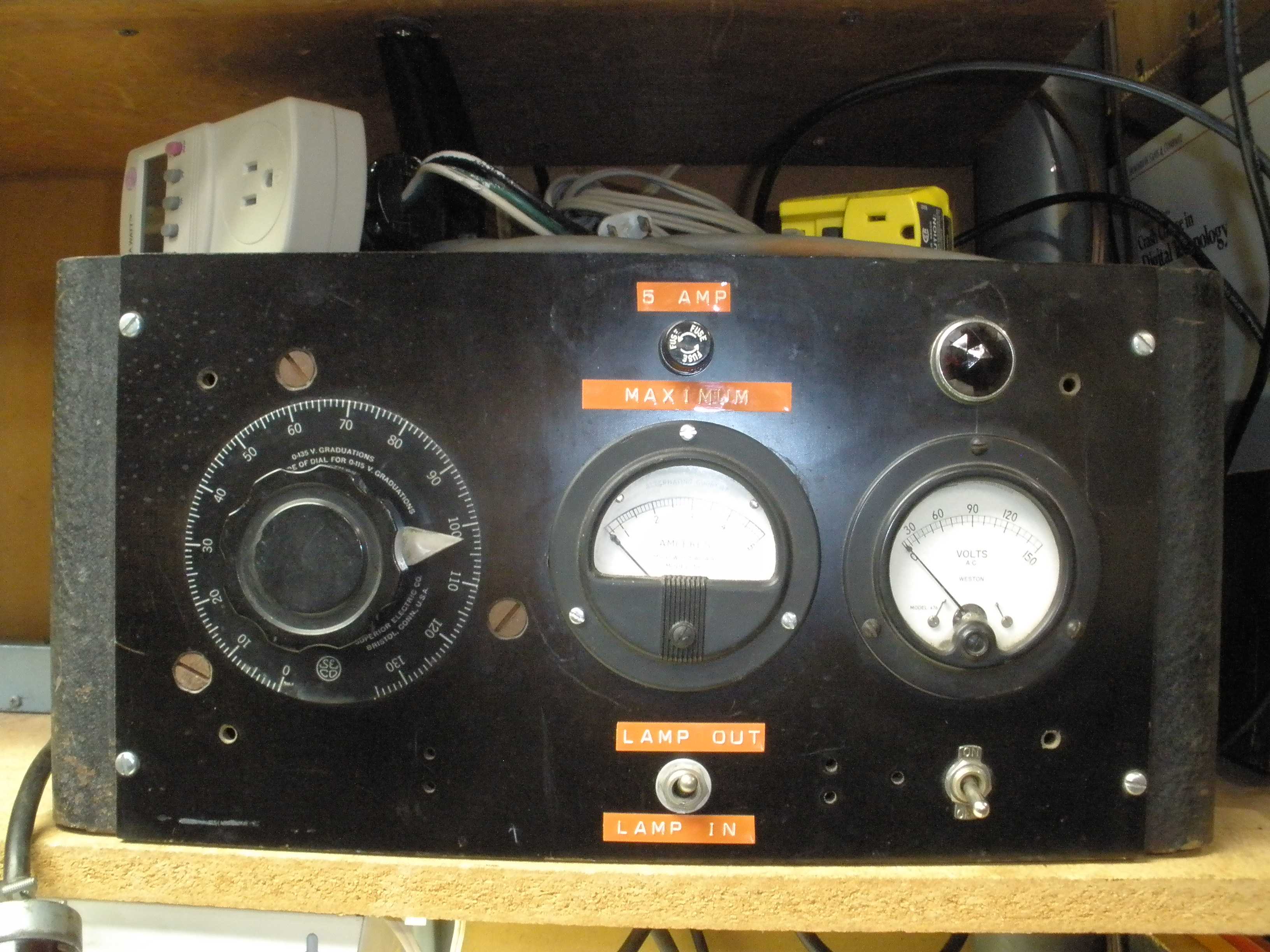
This Variac setup I built has a lamp that can be inserted in the AC line to the receiver under test, to limit current. Remember there are TWO power switches, the clock AND the RF gain control ON/OFF switch. Some of these AC switches fail open, and need to be jumpered around. If you have an original NON "A" version, remove the rectifier tube; bring up the voltage to 50% and read the AC from the HV secondary to see if it is half the value read in the manual. The tubes and panel lights will light dimly, indicating no shorted wiring. Never power up a receiver that has been stored in a damp environment until you let it sit near your wood stove or a warm dry environment, for a week, to bake out any moisture. Gradually creep up on the rated line voltage. If it passes this test, you can plug in the rectifier and do a similar test with the B+ DC voltages. With a tube rectifier, you will not get much B+ until you get to 60 VAC on the line meter. With solid state rectifiers, you can do low voltage tests on the B+, which may reveal shorted tubes, capacitors, or bad wiring.
This HQ-170 came to me in bad shape electrically. Cosmetically, it was pretty good, so it was worth looking it over. The present owner acquired this, with a much smaller power transformer hanging by one wire; he was no rookie, and knew this was a "project radio". He had made a valiant attempt to get it running with an identical sized (wrong) replacement transformer, a separate filament transformer, and a filter choke to reduce the B+ to nearly spec. It was a very good try. But the VR tube did not stay lit, and the voltages (+255 B+ on the schematic) was low. And the filament voltage was off too. Time to see if it is worth proceeding.
If you are working on more complex hollow state radios, you MUST own a decent tube tester. One style does a basic emission test. This is OK for general use. Actually, power tubes like 6L6s and 807s should be subjected to an emission test. Then reduce filament voltage one step while watching to see how fast the quality meter drops; this gives a good idea of life expectancy (due to reserve emission). Really good TV man testers have a "life test" function to prevent call-backs. You can do the same trick with the filament voltage switch. Small tubes are really bad when they fail this test. The other better kind of tube tester measures dynamic transconductance. This puts the tube in a circuit to test the actual gain. I tested all the tubes with a Hickok checker. The Hickok tube checker does BOTH TESTS. The 6AL5 and the last 6BE6 were not 100%, but they were good enough in the position that they were installed, I left replacement till later. In the end, I did not change either one; they did not seem to improve performance when swapped during final test. My test results on tubes agreed with the current owner's tube tester work - good enough to give it a try.
Yes, you can buy a whole set of tubes and swap them ALL. But you are eventually going to spend more money than as if you bought the right tools for the job. This is a "rookie" method. If the set had not been tampered with, that might get it running OK. But what if all the tubes were OK and the circuitry was at fault? That is exactly what happened to this repair job. If the total tube swap doesn't work, now what are you going to do? Maybe you can get away with this sort of shortcut with an S-38, but the Hammarlund HQ-170 is a REAL radio, not a kitchen table set. Yeah, I had to swap a 6C4 that tested good later, so sometimes an educated guess based on experience is better than a tester. The two tubes in the HQ-170 that give me trouble are the 6C4 and the 6BZ6. Buy a tube tester, or buy some beer for a friend who has one (and will let you bring your tubes over once in a while). Anyway, rant is over.....
It was barely running - enough to do a preliminary alignment. The tubes lit up, and the full output of the RF test generator would produce faint audio on some bands. Sensitivity was bad, probably not even 200 uV on the HF bands. The selectivity and sideband selection was a mess. First, I used an audio generator (with a frequency counter) to test the low IF. It was not 60 KHz. It was more like 66 KHz. It was so far off, I had to "walk" it back to spec 1 KHz at a time; NEVER attempt to move it all the way in one step when it is this far off. You may wind up damaging slugs in the IF cans by excessive adjustment. Once the IF was exactly 60 KHz, sensitivity was way up, and the selectivity and sideband selection was near to working. This was a rough alignment, but the results were promising.
I always speculate how the radio got into the condition that led it to wind up on my bench. If only the patient could talk, but its like Veterinary medicine. This radio had a big scorch mark near the VR tube dropping resistor. I have not seen a bad VR tube take out a transformer, unless the fuse was increased to a ridiculous size. The radio still smells burned. Sniff stuff you buy at a swapmeet, you might learn something important. The filter can was not bad. It had not been replaced either, thankfully. So it was not the filter condenser that caused the burn out. Subsequently, someone (a second owner) that did not know what they were doing attempted a transformer replacement. Then it went to a swap meet and wound up in my friend's cellar. He did the courageous transformer swap, and he got sick and had to abandon the project. He did not have time to mess with the alignment, and knew better anyway. I knew this radio was on his "bucket list" and friends do what friends do.
Well that is the forensics for the power supply work. How did the 60 KHz IF get that many turns off on the coils? Screwdriver mechanic. The ridiculously small transformer my friend found was a clue. Rookies will turn all the adjustment till they get so far out of whack, you have to go to extremes to get them back in range again.
IMPORTANT RULE OF THUMB: If you are trying to get a radio running, do not go more than 1 turn on any slug in the can, unless you have good test equipment and really know what you are doing. If you do not have a lot of test gear, but have a good sense of repair and a bit of experience, you can "touch up" an alignment "by ear". But do not go more than one turn in the coils. Experience tells you when to STOP and get the right tools or get someone who does to help.
WHY IS THIS IMPORTANT? Think about it. If the radio was running when it left the factory, the slugs should be within maybe half a turn of correct. No normal tube replacement would require such drastic twiddling. If you run the slugs out of their normal range, the cheap paper coil form will not have any wear on it, and the slug may jam way out of adjustment in the tighter range of the coil. Now you are really - well - screwed. The 60 KHz IFs were way out of adjustment. The 15 meter oscillator coil was destroyed, probably in the way I just described. Not knowing when to quit, the rookie barreled ahead and kludged in the replacement coil. Then the transformer failed, possibly by some act of the rookie. Without the right transformer, he quit. Then it came to my friend. This speculation may seem irrelevant, but it may give clues on what to look for during the repair. Anyway, we have a job to do...
 2nd Conversion Oscillator Xtal. I checked the 455 KHz IF, using the technique described in the Hammarlund manual, and it was off too. That rough alignment dramatically improved performance on 160 and 80, the double conversion bands. This frequency is even more critical in the HQ-180, which has a crystal filter in the 3.035 MHz IF. The crystal conversion oscillator and the crystal filter do not move. Everything else must match those, or it will not work properly.
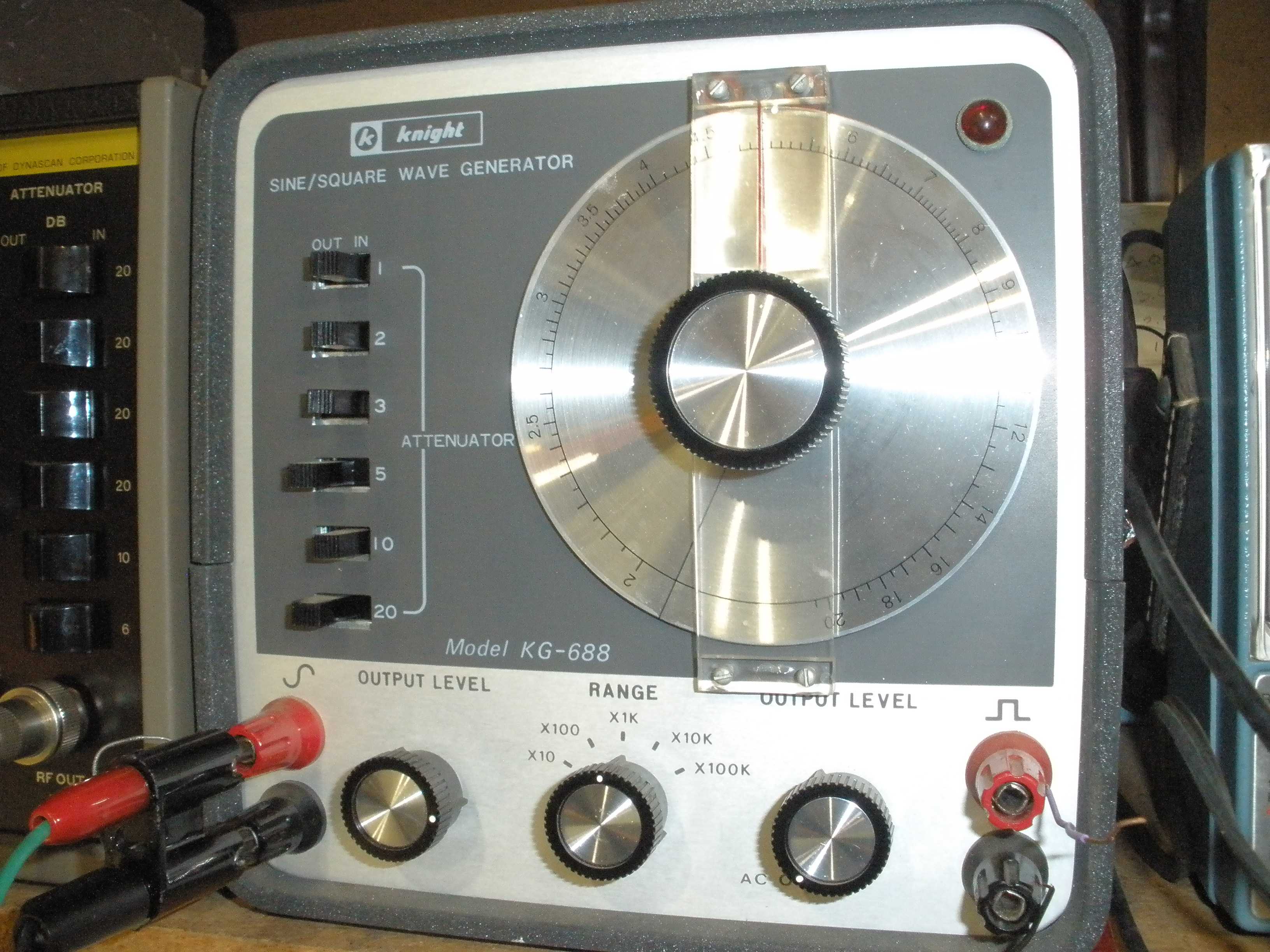
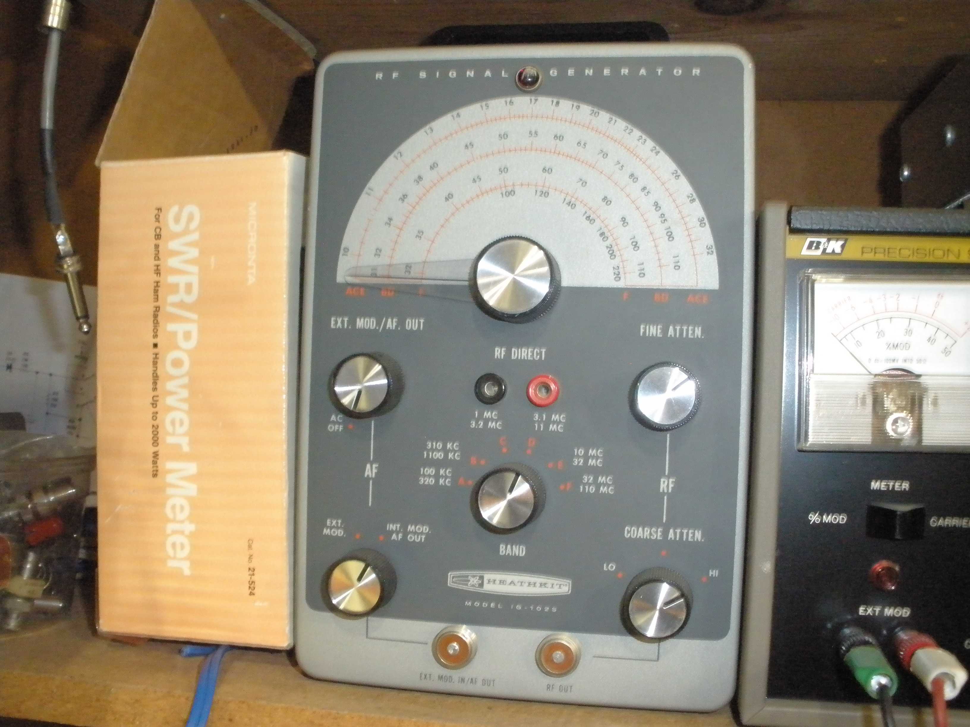
If you do not have the right equipment (60 KHz generator, frequency counter, crystal calibrator with multiple frequency outputs, maybe a sweep generator) anything more than a minor touchup can possibly make a minor problem into a major problem. An "old school" tool, the Grid Dip Meter, is often useful. Many modern hams do not even know what it is. A "Sinadder" that measures the signal to noise ratio, or an HP THD analyzer would be great to have, if I find one at the right price. This B& K E-2000 RF generator and a home brew crystal marker generator are what I use for signal sources. Yes, you have a 100 KHz marker in the receiver. But if the alignment is more than 100 KHz off, you need a marker at 1 MHz so you can find the right one. On 10 meters, you may need a 2 or 4 MHz marker if it is way off. This B & K E-2000 RF generator has calibrated output down to 1 uV or less. For a high performance receiver like the HQ-170 & HQ-180, you will also need a good 50 ohm switchable calibrated attenuator box, to reduce the signal lower than the front panel switches allow. The B & K E-2000 also has both 100 KHz and 1 MHz markers and an internal speaker so the zero beat is audible as you set the tuning dial. The audio generator can be used for the 60 KHz alignment, using a frequency counter to set it to the exact frequency. You also need a good VTVM. A Heathkit is fine, but I like this large scale meter on the RCA VTVM. I also have a HP 410 meter for the heavy lifting. This meter is great for RF measurements.
http://www.ohio.edu/people/postr/bapix/HP410B_2.htm
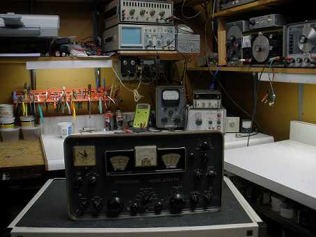
A well organized work area and good tools are necessary for quality work on a radio this complex. Some people are fortunate to have HP or tektronix gear, but I find that quality made better grade consumer gear works well, with less cash outlay. All test equipment should be refurbished and calibrated, or you will get questionable results, and spend more time fixing your gear than enjoying using it.
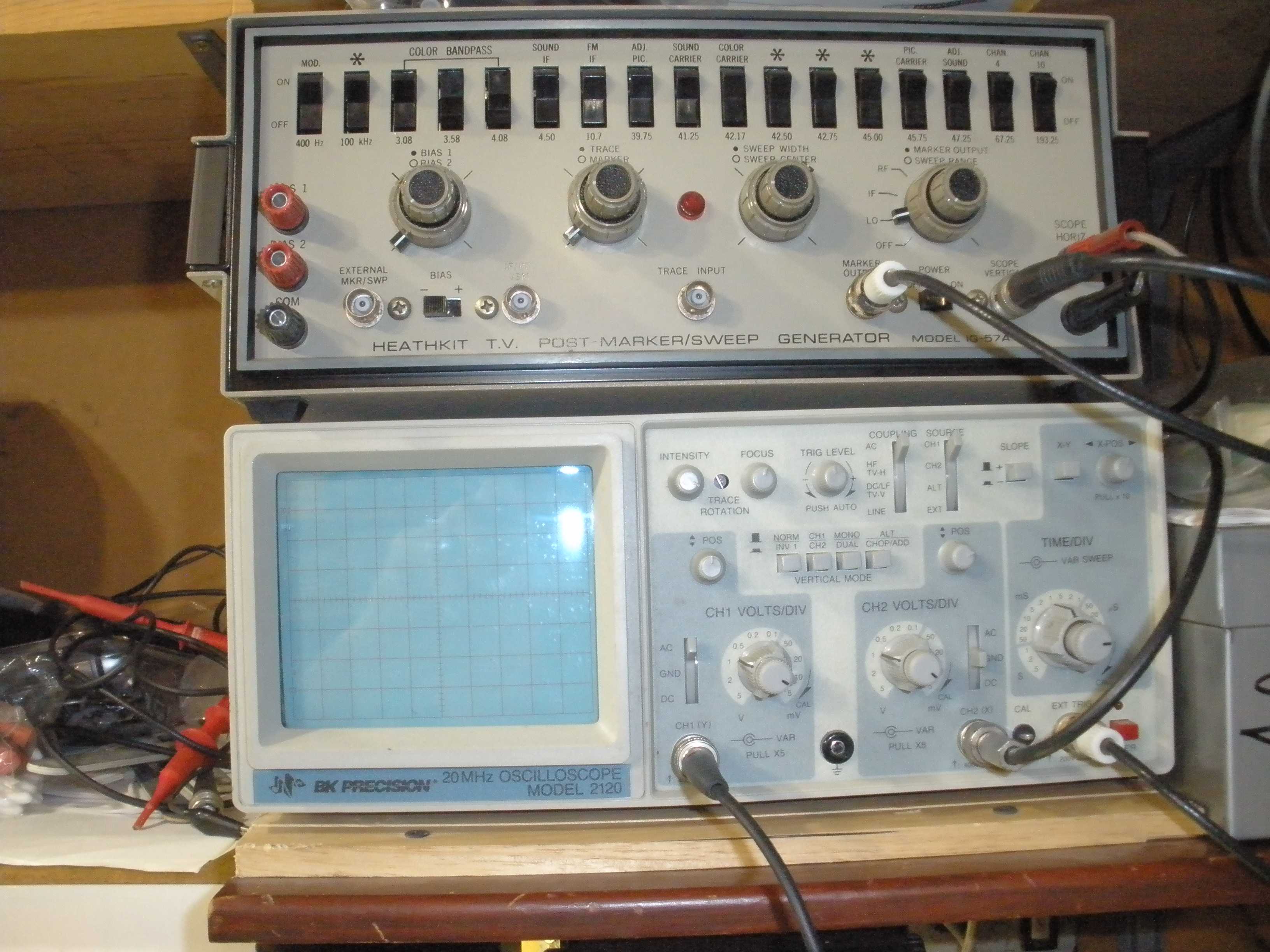
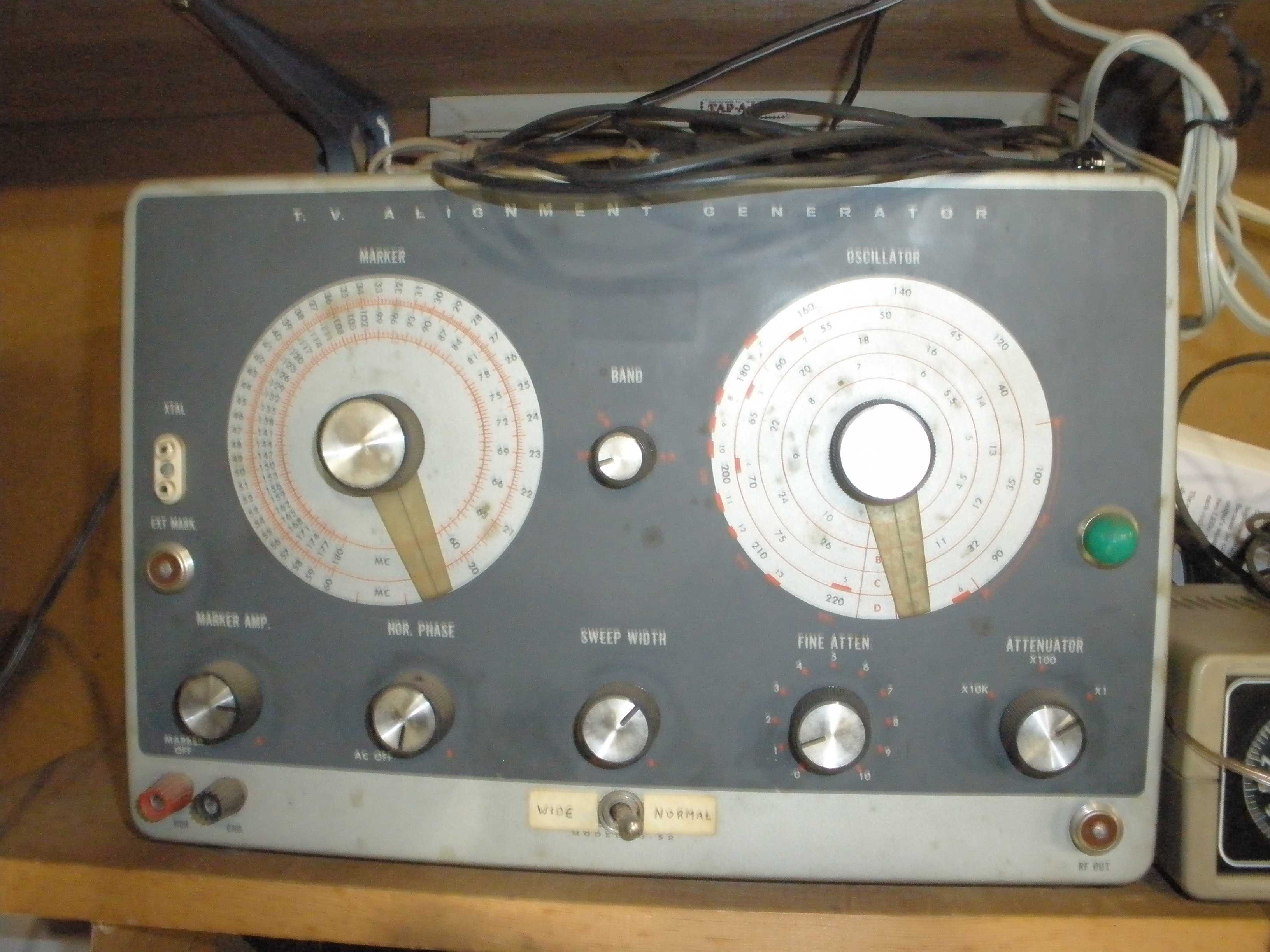
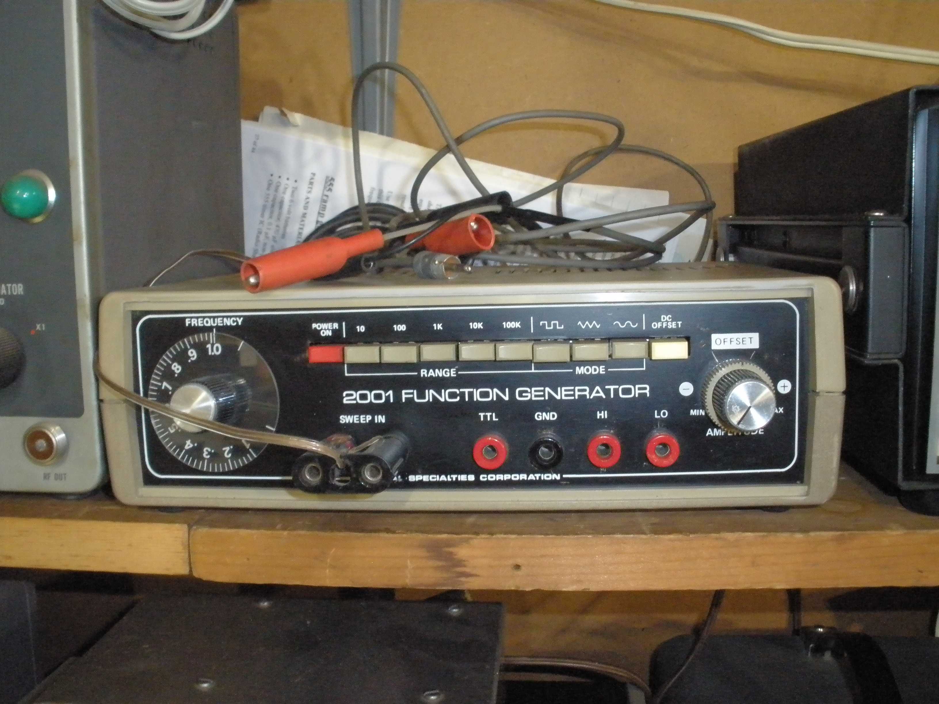
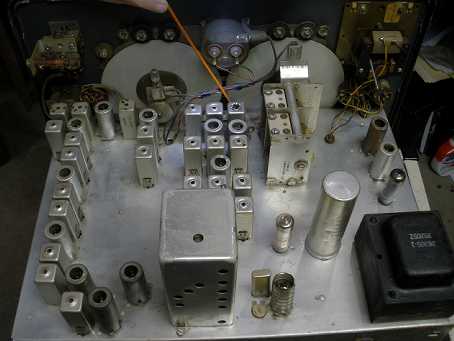
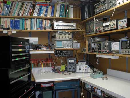 Orderly work area 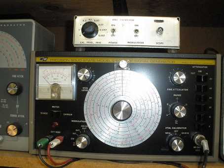 B & K E-2000 & xtal calibrator 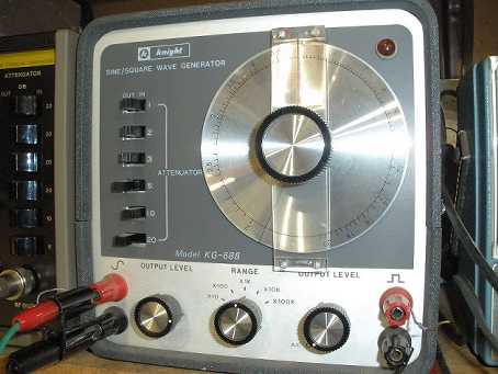 Audio generator 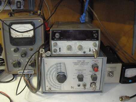 HP counter, HP 410 VTVM, Tektronix generator 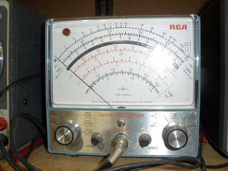 RCA VTVM 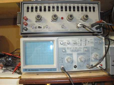 Heath sweep generator & B&K scope 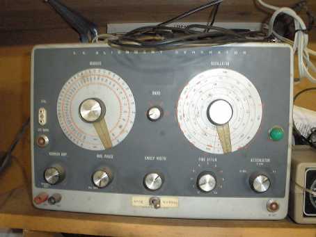 Heath sweep/marker generator 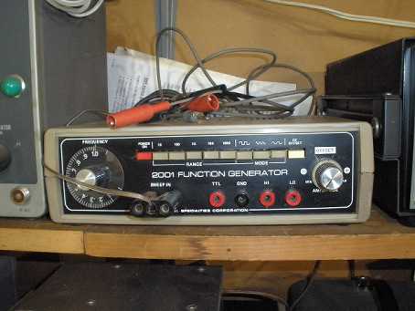 Audio/low IF sweep generator  Heath RF generator, with "trick" jacks Then I performed the 3.035 MHz IF alignment per the manual. Now 40 meters was sounding better too.
This procedure will allow you to determine if the low IF section of your Hammarlund HQ-170 or HQ-180 is operating properly, without expensive test equipment. It is a great tip if you are trying out a radio to see if you want to buy it. I used it at this point in the repair on this HQ-170, to make sure I was on the right track.
First, you must have a VERY stable signal (crystal oscillator) that is at a very low level, on the order of 10 uV. You may improvise this by temporarily disconnecting the output wire from the internal 100 KHz oscillator in the HQ-170 from the antenna of the radio. Just wrap a turn or two around the antenna wires to reduce the coupling to the radio to about 1 pF or so; this should result in about S7 to S9, NO MORE. Warm the receiver up for half an hour to stablize it. Select 80 meters and tune in a calibrator signal to verify you got the level correct. Select SSB and tune for zero beat in the case of an A version. In an original non A model, set the BFO knob to 12 o'clock in CW mode (there is no separate SSB mode).
IMPORTANT: In all the tests described below, neither the main tuning or vernier tuning must be touched at all, other than to maintain zero beat with the signal generator or crystal oscillator.
To prevent interaction with the NOTCH tuning, set its frequency adjustor to maximum clockwise. Set the other resistive notch control (DEPTH) to maximum clockwise. This reduces the possibility the notch will influence the results observed in the following tests. If you know how, check the operation of the notch tuning first, to see if it is aligned properly. This is covered in the normal operating procedure of the user's manual. The NOTCH DEPTH is on the front panel of the HQ-170 and inside the cabinet opening on the right front in the HQ-180.
Set the Sideband selector to BOTH. Observe the S meter as you switch from 3 KHz to 2, and 1 KHz. The S meter should not deflect more than 2 S units, preferably more like 1 S unit. In each band width position, rotate the sideband selector to BOTH, UPPER, AND LOWER. The S meter should not differ more than 2 S units, more like 1 S unit from each sideband selection.
The 0.5 KHz band width is a special case. It is normally aligned in USB and 0.5 KHz when using the method described in the Hammarlund service manual. Set the sideband select to USB. Set the band width to 1 KHz. Observe the S meter. Switch to 0.5 KHz. The variation of S meter should be less than 2 S units, preferably more like 1 S unit. Now in 0.5 KHz band width, switch between USB and LSB. The S meter should be less than 2 S units difference, more like 1 S unit.
IMPORTANT: Do NOT expect the switching between BOTH and either USB or LSB while in 0.5 KHz to yield similar results to the above tests. It is normal for the BOTH position to yield markedly lower S meter reading than USB or LSB while 0.5 KHz is selected. They ALL do that. If you want 1 KHz bandwidth, use 1 KHz and USB or LSB.
Final test: While still zero beat with the low level reduced crystal oscillator signal, exercise each position of the band width selector and each combination of the sideband selector (except as noted above for the 0.5 KHz and BOTH). Tune the vernier tuning (not on some HQ-180 early models) off to each side to the full +3 KHz to -3 KHz. Observe the sound of the beat note and the action of the S meter. It should fall off smoothly to one side when using USB or LSB. The other sideband should quickly disappear. In BOTH, it should be smooth and symmetrical; 3 KHz on BOTH may not quite live up to your expectations, but it should be close. Remember the above caution that BOTH in 0.5 KHz will not work right, even when the receiver is operating normally to specs.
If the receiver under test passes these tests, low IF alignment is NOT indicated, and you should leave it alone! If you wish, touch up the RF and mixer. Adjust the oscillator ONLY if the dial calibration cannot be brought in with the small knob to the right of the tuning dials. This is not a frequency standard. Excessive messing with the slugs in these paper coil forms will lead to misery that you do not want to experience.
Credit for this clever test is given to Pete, K7PP, who has a number of youtube videos on Hammarlund repair. See:
https://www.youtube.com/watch?v=DD-kIXIUX-s and
https://www.youtube.com/watch?v=4l1hWNvPe2g.
Do not forget to reconnect the crystal calibrator to the proper point. Otherwise weak injection will result on 15 and 10 meters. Remember to set the NOTCH DEPTH back to its normal point.
In the case of an HQ-180, I recommend that you try the "Final Test" step on the highest frequency band. The triple conversion mode is enabled only on the highest frequencies. This allows you to see if the 3.035 MHz crystal filter is interacting incorrectly. Sweep alignment of that portion (HQ-180 only) is tedious. Do NOT attempt it without a sweep generator. This test is not required in the HQ-170 because it does not have a 3.035 MHz crystal filter.
IF YOU FIND PROBLEMS: If the signal level is incorrect, but the selectivity roll off of signal seems OK, check the carbon resistors on the SIDEBAND and BAND WIDTH switches. If they are out of spec, change them first. It is cheap and easy. These resistors correct the overall IF gain for the insertion loss inherent in the narrow filter operation. Make sure the switch is clean. All of the low IF slugs should tune normally (not at the end of the range, where they can become jammed in the coil form). The oldest models of HQ-170 MAY have the open style mica capacitors which are known to be flaky. If one can does not tune normally, open it up, using the procedures shown on K7PP videos and replace the bad capacitor inside the can with a new dipped mica style. The Dipped Mica Capacitors on the switches (not the old square postage stamp WW2 types) are pretty reliable. It is unwise to go nuts changing them as a first step. Read the disclaimer below before you go ahead with a "shotgun" complete replacement of all mica capacitors in the low IF.
DISCLAIMER: If you do not find your measured IF response curves match the curves in the printed user manual, do not be surprised. I imagine these curves were obtained from a hand tweaked engineering prototype. Normal production tolerances in practice do not yield lab results. The years take a toll also. Enjoy this receiver for what it is, a stunning step forward for its time. Realize there was a reason that all this tuned circuit mystery was replaced by reliable crystal and mechanical filters. For some reason, the NC-303 and SX-101 seemed to perform better and were easier to align than the HQ-170 with the low IF technology of the time.
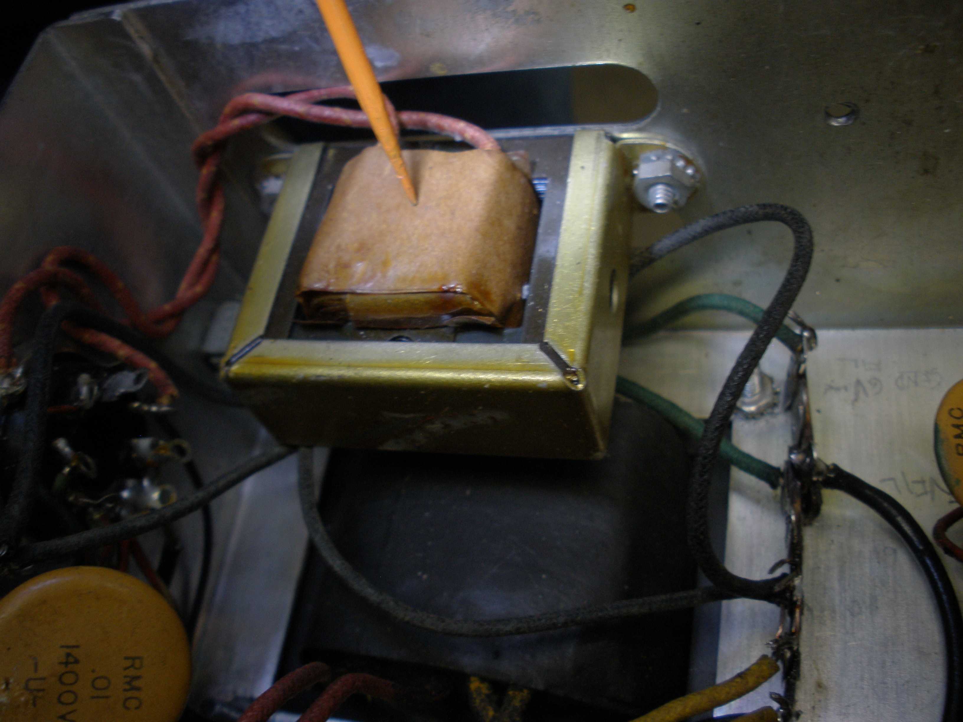
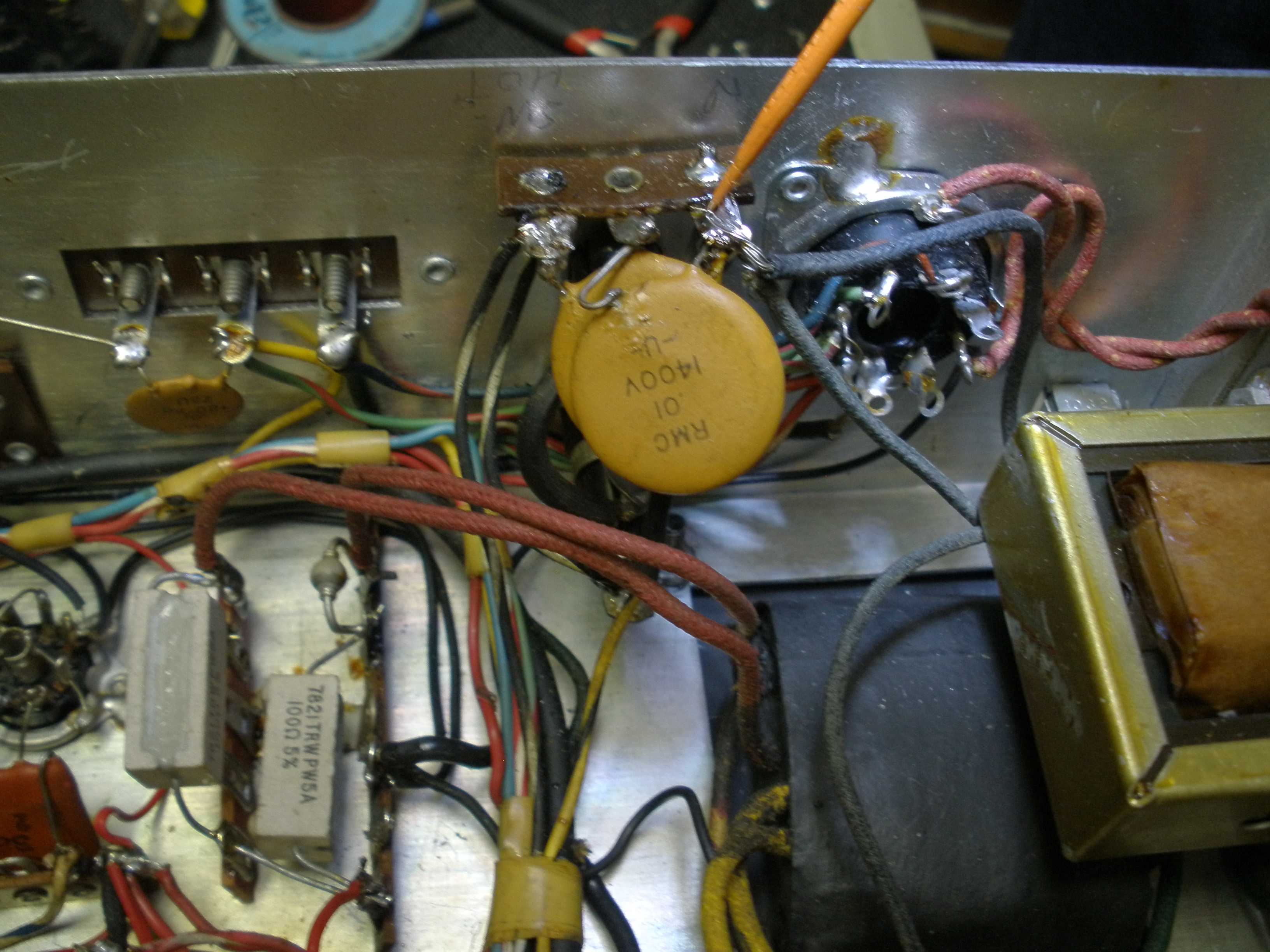
At that point, I had a HQ-170 power transformer version -1, for a non-A radio. This earlier transformer was not designed to power an accessory like the accessory 2 meter converter that was field installed in this radio. I disconnected the 2 meter converter power and signal wiring, wrapping it up in a ty-wrap to the harness, in case future installation was desired. Perhaps one day, some one will come into possession of the correct -3 version transformer. It really helps to read the manual - even the parts list!
Details are important! Putting in the dash 1 version transformer, with the 2 meter converter accessory, would have drawn too much filament and B+. The replacement transformer would have burned out - AGAIN! Getting another unobtainium transformer would have been unlikely. Possibly back to the drawing board with the substitute transformer would have been another round of power supply design, which may not have succeeded. Haste makes waste; attention to details is essential. Knowing the difference between the models of a radio, and the evolution of its design can keep you out of trouble.
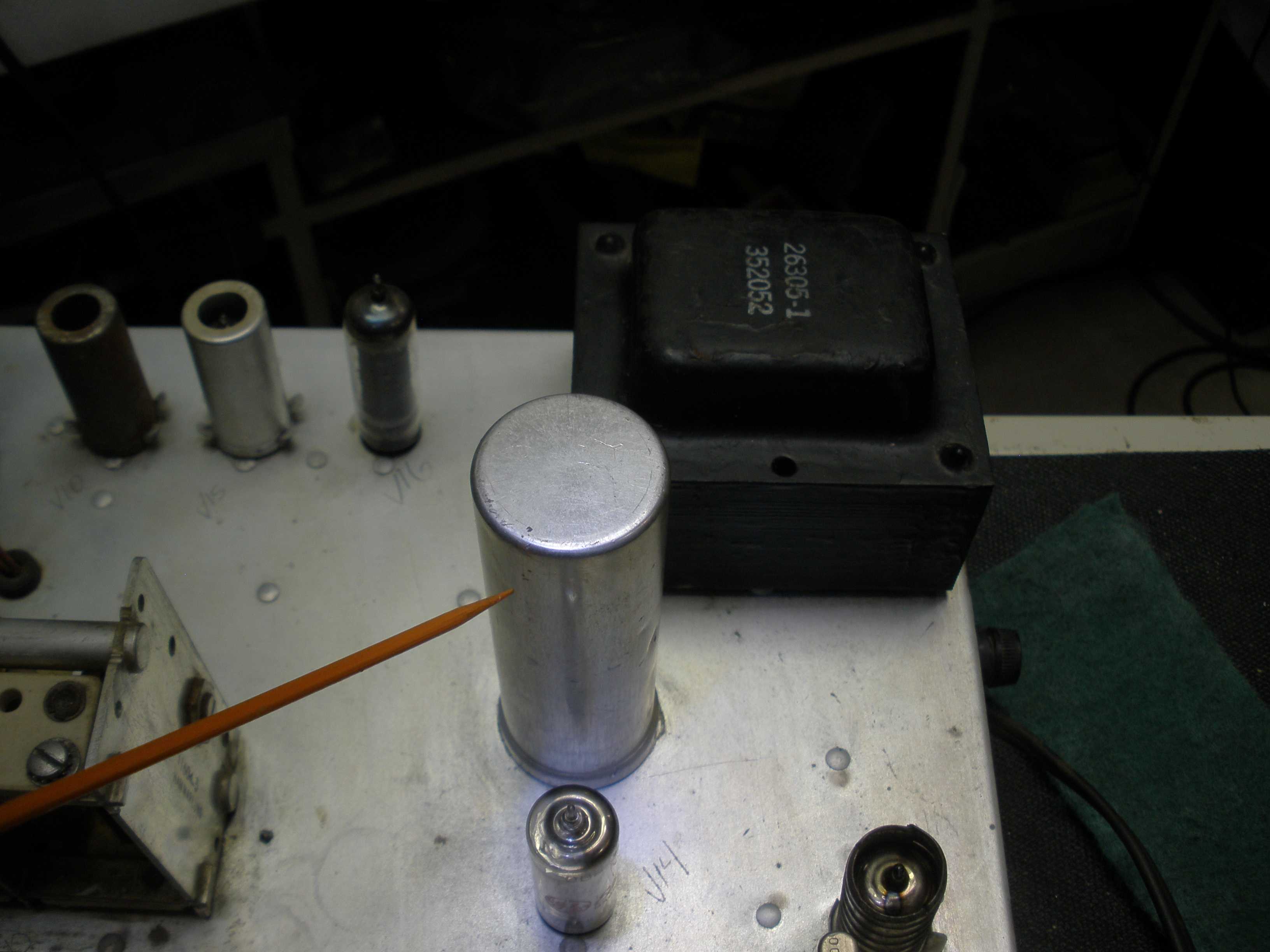
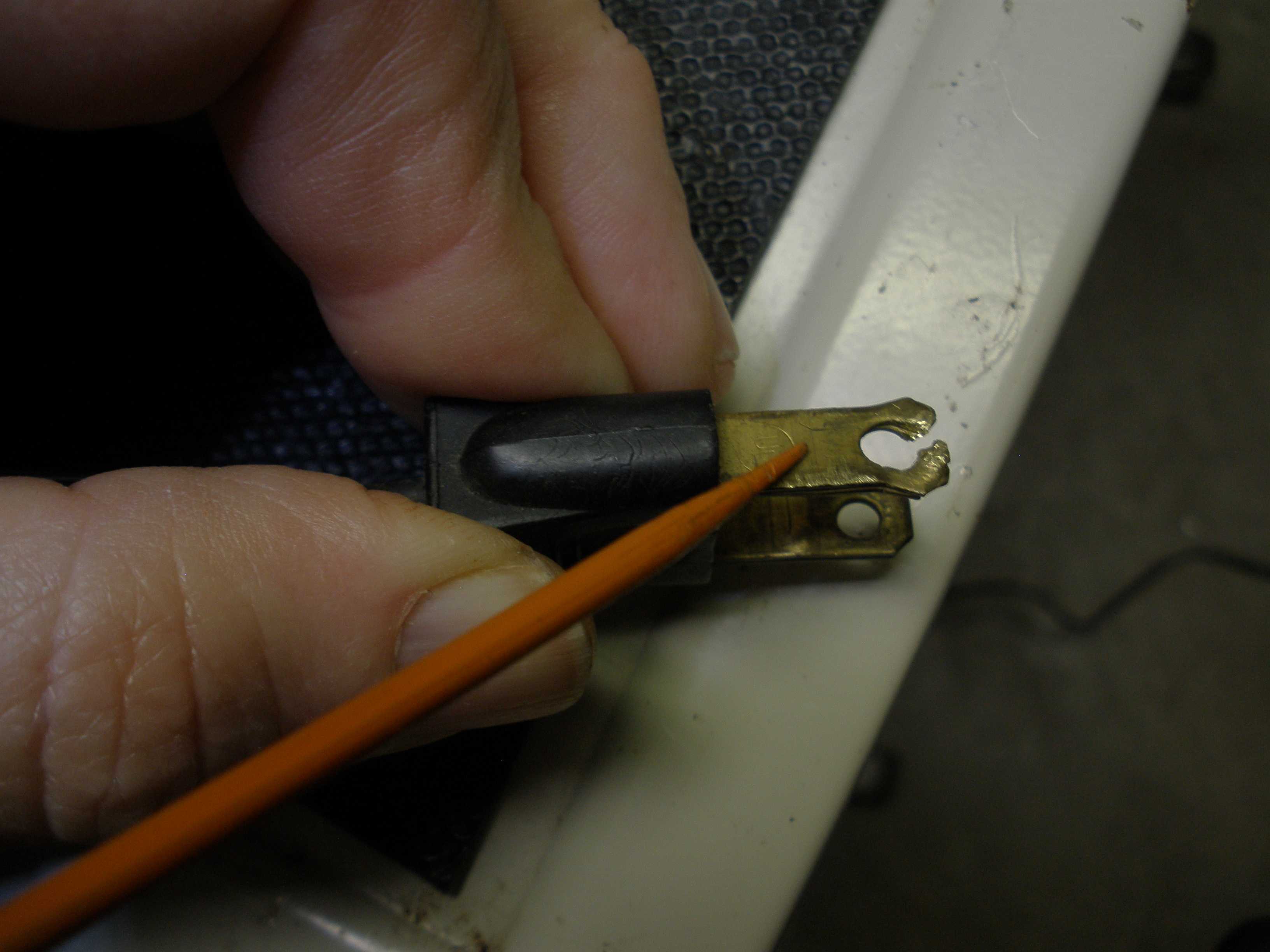
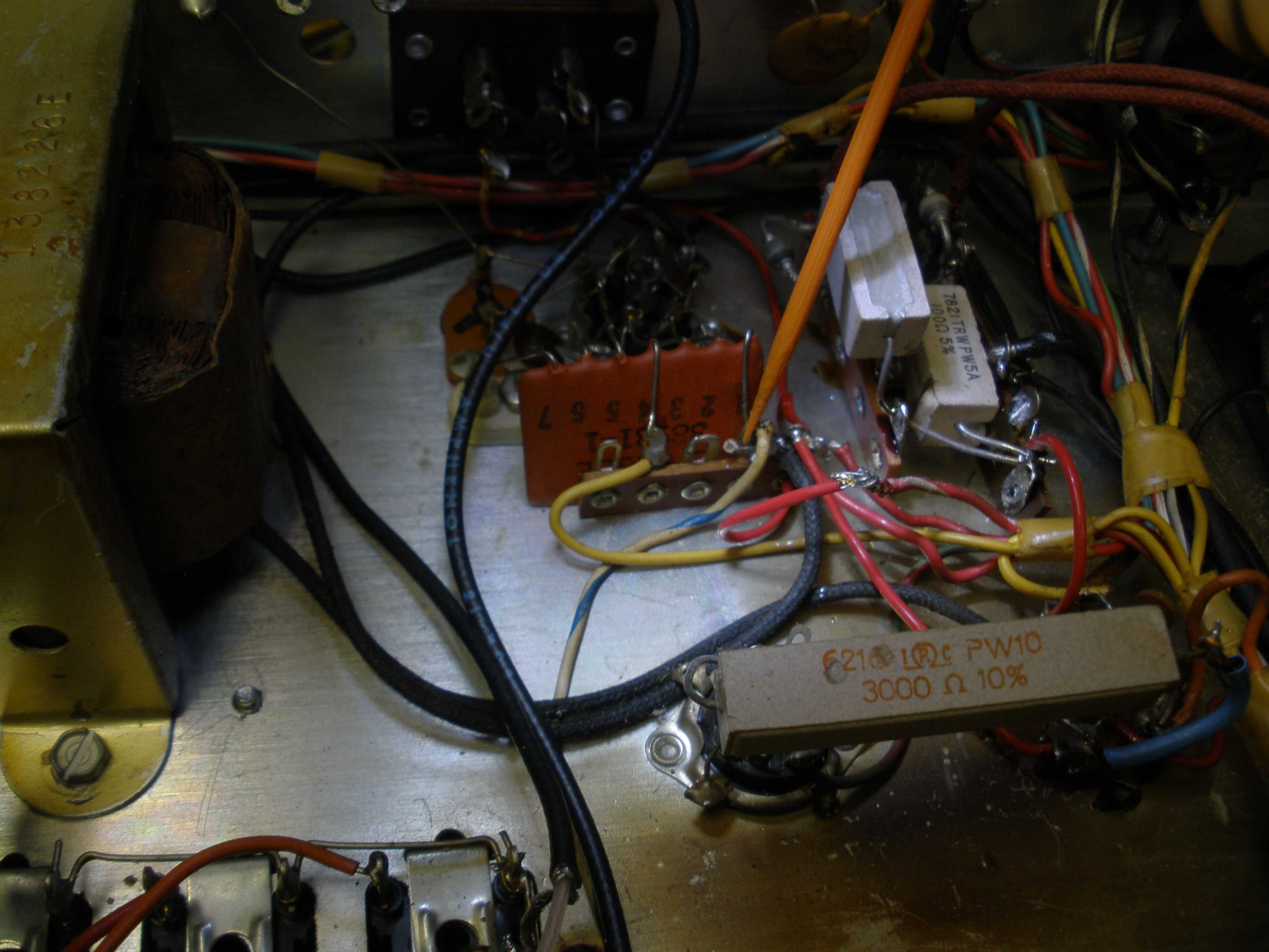
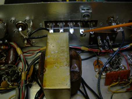
I installed the new transformer, tracing all the wiring against the Hammarlund schematic. While I was at it, I wired the small 6 volt filament transformer for the 6BE6 and 6C4 oscillator to make it power down in the OFF position. This prevents premature tube failure, due to being always on. Fortunately this was not a european radio with the 220 VAC option. The new transformer ran cool, after being on for hours. We do not want another transformer failure. I also used a Timtron trick. The -1 transformer had a 5U4 tube, so it needed a filament winding of 5 VAC. I wired that up to the primary, bucking the AC line voltage to reduce it. This makes internal voltages correct on modern 120 VAC; filaments at various points are exactly 6.30 VAC, and the +255 VDC is exact, at 119 VAC. Use a variac and set the line voltage to 105 VAC. Test the B+. Swap the yellow wires to use the opposite phasing. Test it again. Use the connection that results in the LOWER B+ for the same 105VAC. Retest it at full line 120VAC; the voltages should be very close to the spec on the schematic. I used a 100 Ohm 5 Watt resistor in series with each diode, like those shown on Woody's photo web site referenced earlier. This is important to protect the diodes from failure due to surge on power up. It also brings the voltages closer to spec.
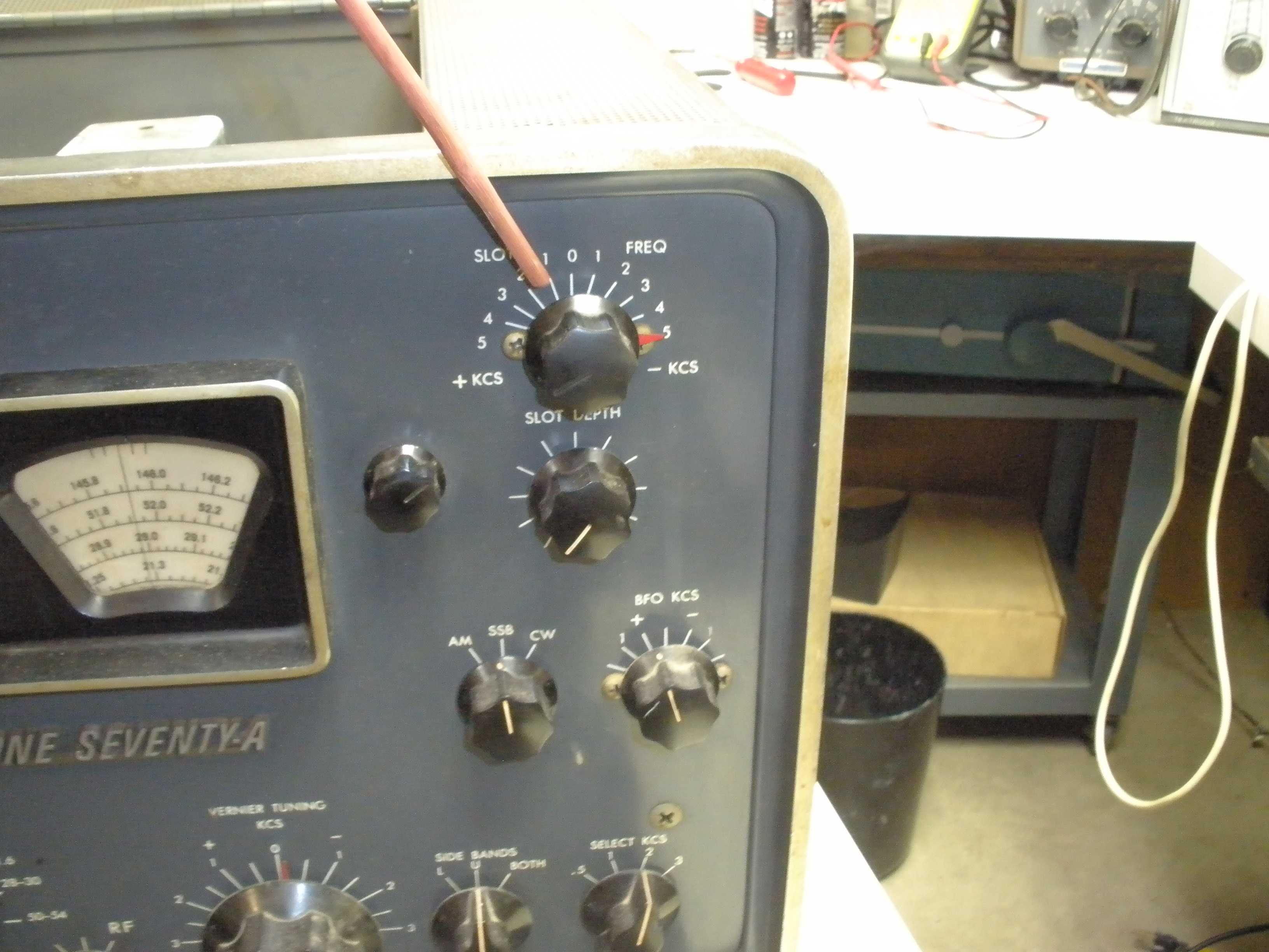
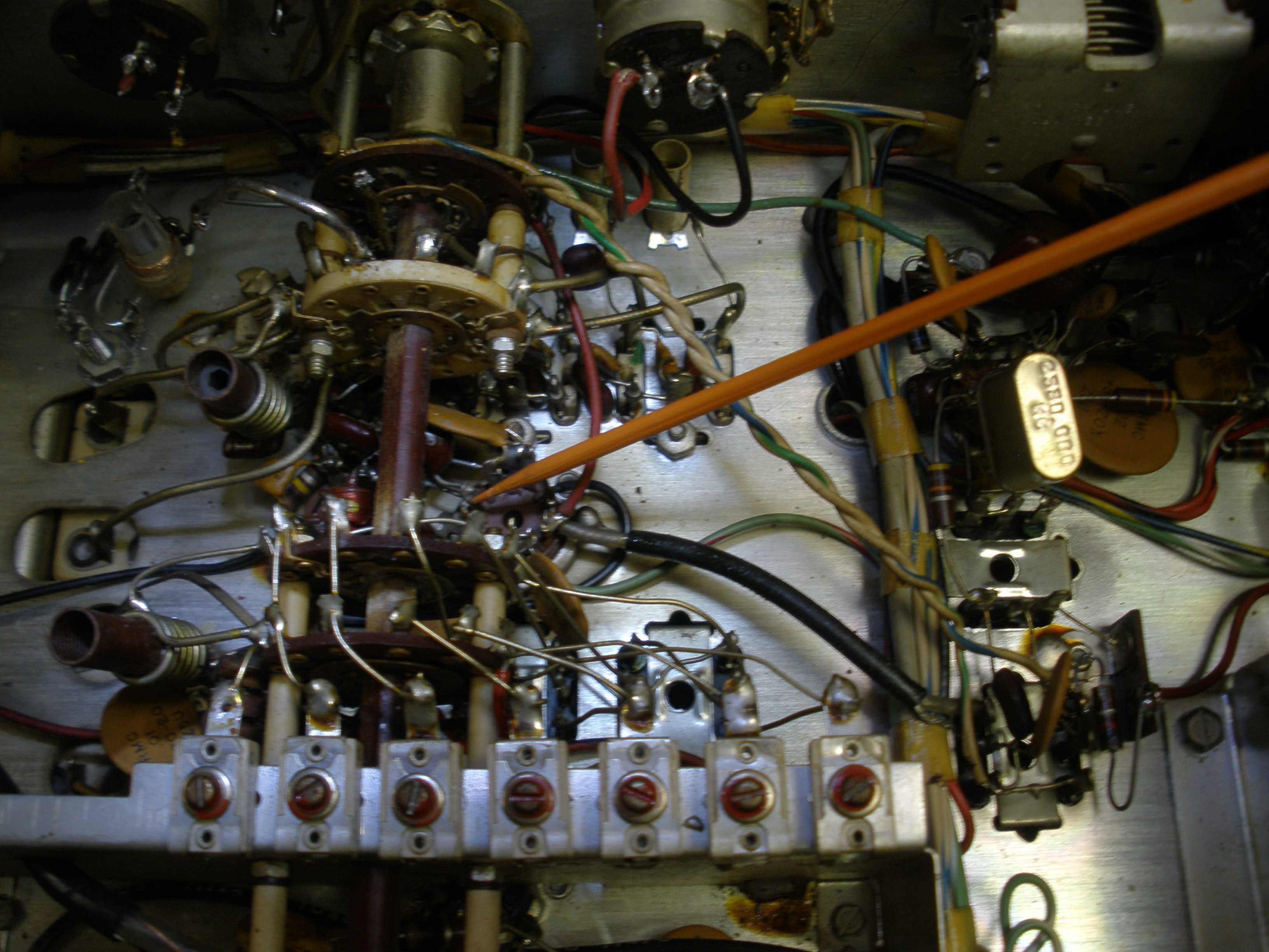
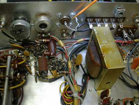
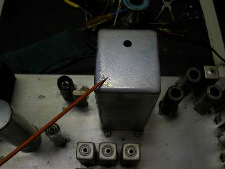 2 meter converter 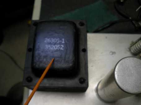 Power Transformer 26305-1 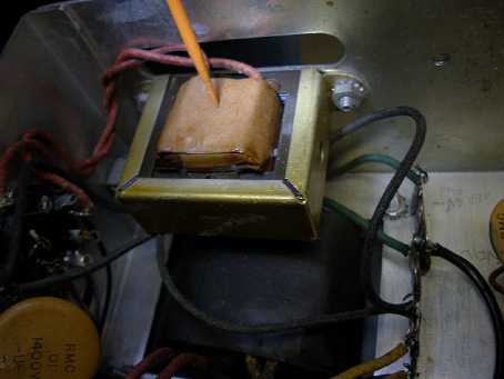 Filament transformer  Neutral wire 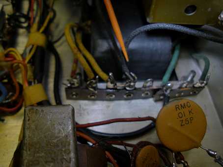 Hot wire (switched)  Yellow 5VAC bucking  100 Ohm & diodes 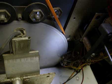 Correct clock installation. This clock was an after market installation. It was installed with the clock flange behind the tuning dial. Note that the correctly installed clock flange is nearest the front panel and the tuning dial goes in BACK of the clock flange, to prevent the scoring of the dial you see here. You may have to loosen the set screws on the tuning dial to set it to clear the clock flange as well as the AVC switch. Be sure you do not mess up the calibration stop on the hash mark of the tuning dial; it should be at the point the capacitor is fully meshed, and the rotation stops mechanically. Otherwise, dial calibration with the electrical adjustments will be nearly impossible.
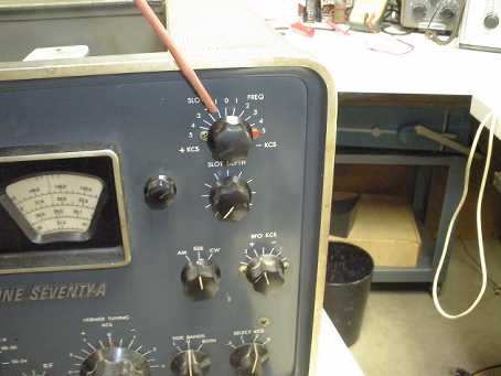
Small knob to right of the tuning dial adjusts the cursor in the window. The small calibration knob to the right of the tuning dial containing the 10 meter band is used to make minor corrections to the cursor position when using the crystal calibrator. BOTH tuning dials should be in sync at the lowest frequency. Also, the cursors moved by the small knob should be at the same point in the windows. Often the cursor plastic wedges wear where they sit on the tuning shaft. Then they will be impossible to synchronize with the center of the front panel opening. On the web, there is a video on youtube showing how to correct this issue, by cutting the metal strut that connects the two cursor assemblies. Fortunately, this radio did not require such drastic attention.
ONCE AGAIN, DETAILS ARE VERY IMPORTANT: Before beginning RF alignment of the front end, and final dial calibration, all these mechanical details MUST be correct FIRST! Otherwise it is nearly impossible to get into adjustment using ELECTRICAL controls in a vain attempt to fix a MECHANICAL problem. Sequence of repair or adjustment is also important.
 Line cord polarizing. Many people put a 3 wire plug on these older radios. I often use a polarized plug to connect the neutral (wider side of the line cord plug) to the transformer on one side. The other side of the transformer, the AC power switch, and fuse connect to the HOT side of the line cord (narrower pin). Here is how to polarize an existing non polarized AC plug, if the plug has holes in it. Get sharp heavy duty wire cutters and split the end of the pin near the end of the plug. Spread the plug pin apart on either side of the hole enough that it will still fit in the neutral hole of an AC socket, but not fit into the narrower hot side of the AC plug. The chassis is grounded through the antenna coax, and the connections to the T/R switching shared with the transmitter. A 3 wire plug is still nice to do, but this is a work around using an existing plug, and improves safety significantly.
 Next step is the front end alignment. Everything went according to the manual, except 6 meters was completely dead. Also, a previous owner had attempted repair to the 15 meter oscillator coil by putting in an outboard coil, near the bandswitch. Why would you do this? The HQ-170, as I said previously, shares two oscillator coils inside a common can. In this case, 10 and 15 meters. Ten worked fine. Why would I risk damaging the working band to take it all apart and damaging the good 10 meter coil? Also, in the HQ-170, all the coils are grouped close underneath the band switch. (The HQ-180 uses individual oscillator coils that you can get to easier.) You would have to be really determined to remove the front panel and bandswitch to get to the coil and then remove it from the chassis. Then you would have to have the extreme good luck to have the exact unobtainium replacement part. Otherwise, you would have to disassemble the broken coil assembly and repair it, possibly rewinding the bad coil. Or possibly wrecking the working part of it. When possible, I prefer this simpler type of repair, fix only the problem, do not introduce new problems. I did this in my HQ-145. Look at the far right half way down on this photo. I installed an oscillator coil for the broadcast band (much less critical than 15 meters) just behind the switch deck near the front panel. The radio works as good as new, and I did not break it worse than it was in the first place.
 The original technician was absolutely on the right track. But he seemed to be digging at the top of the 10 & 15 meter IF can; why? You could only damage the working part of it.
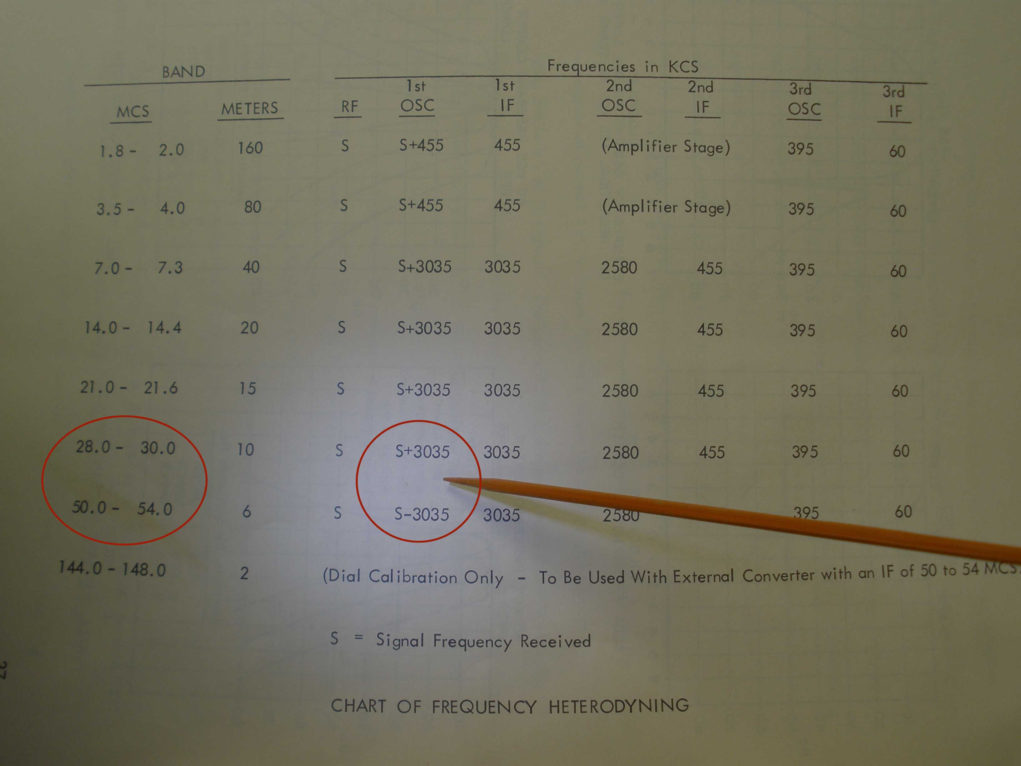
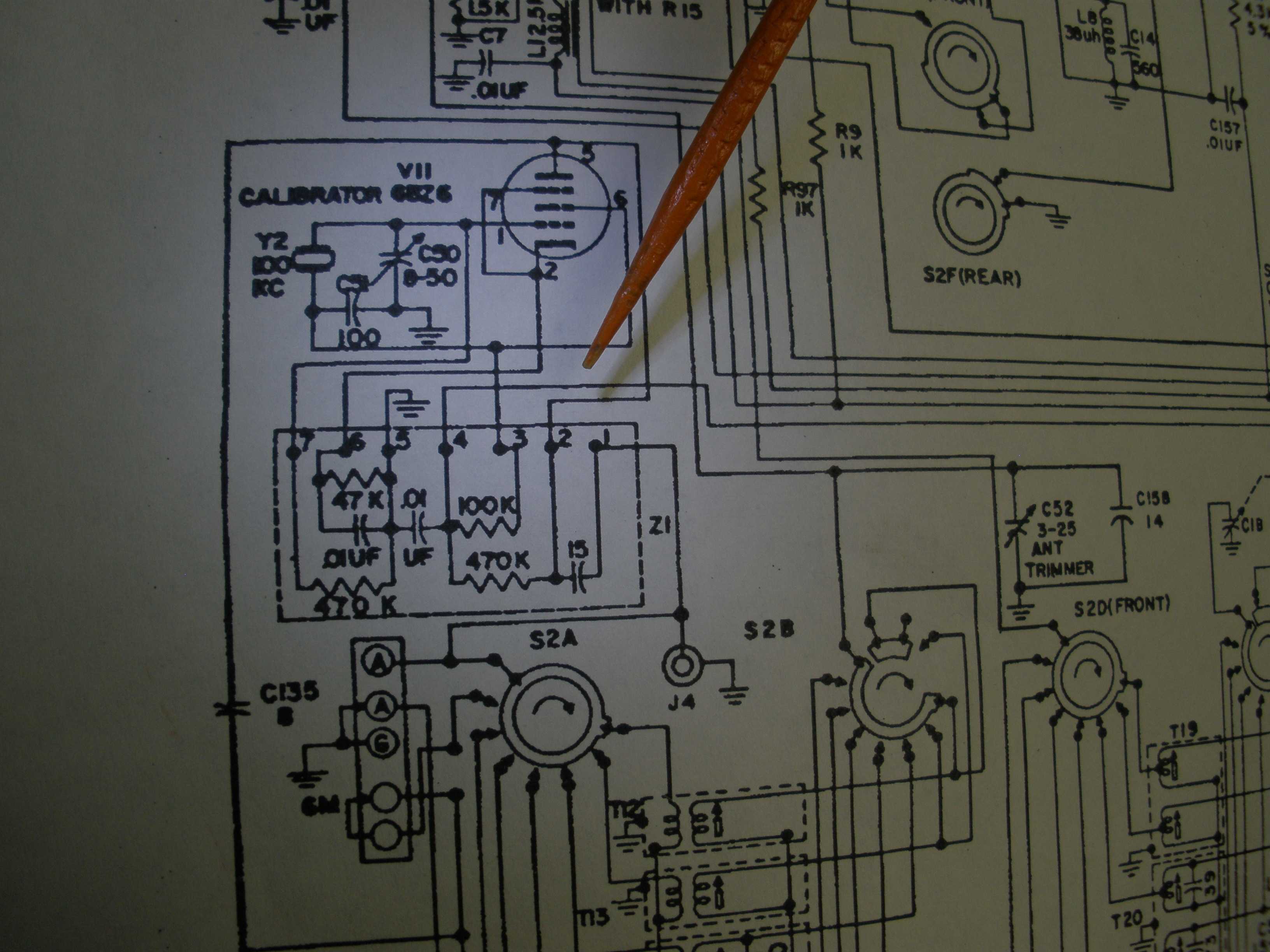
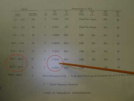
I got out the Grid Dip Meter, and checked the 15 meter oscillator. It would drop out of oscillation intermittently. I also discovered why tracking and sensitivity was terrible: 15 Meters had the injection on the LOW side, below the signal because the coil had too much inductance. The original tech did not have the gear to work on this level of receiver, and chased his tail, possibly destroying the original coil and misaligning the low IF stages. Do not work on equipment that is way above your range of experience, without help from an experienced mentor. And know when to give up and ask for help. Anyway, the HFO injection offset is backwards, it should be ABOVE the signal by 3.035 MHz. The manual states that on all triple conversion HF bands the oscillator runs on the S(ignal) PLUS 3.035 MHz. Only on 6 meters, the oscillator runs on S(ignal) MINUS 3.035 MHz. The 6C4 oscillator would drop out of oscillation intermittently. This tube had tested good in the beginning. But in this radio, 6BZ6s and especially 6C4s are very fussy. I swapped it out. Quelle bonne surprise! 6 meters came back to life (as good as it can in a HQ-170). Also, 15 meters did not drop out of oscillation as badly, but it was still terrible.
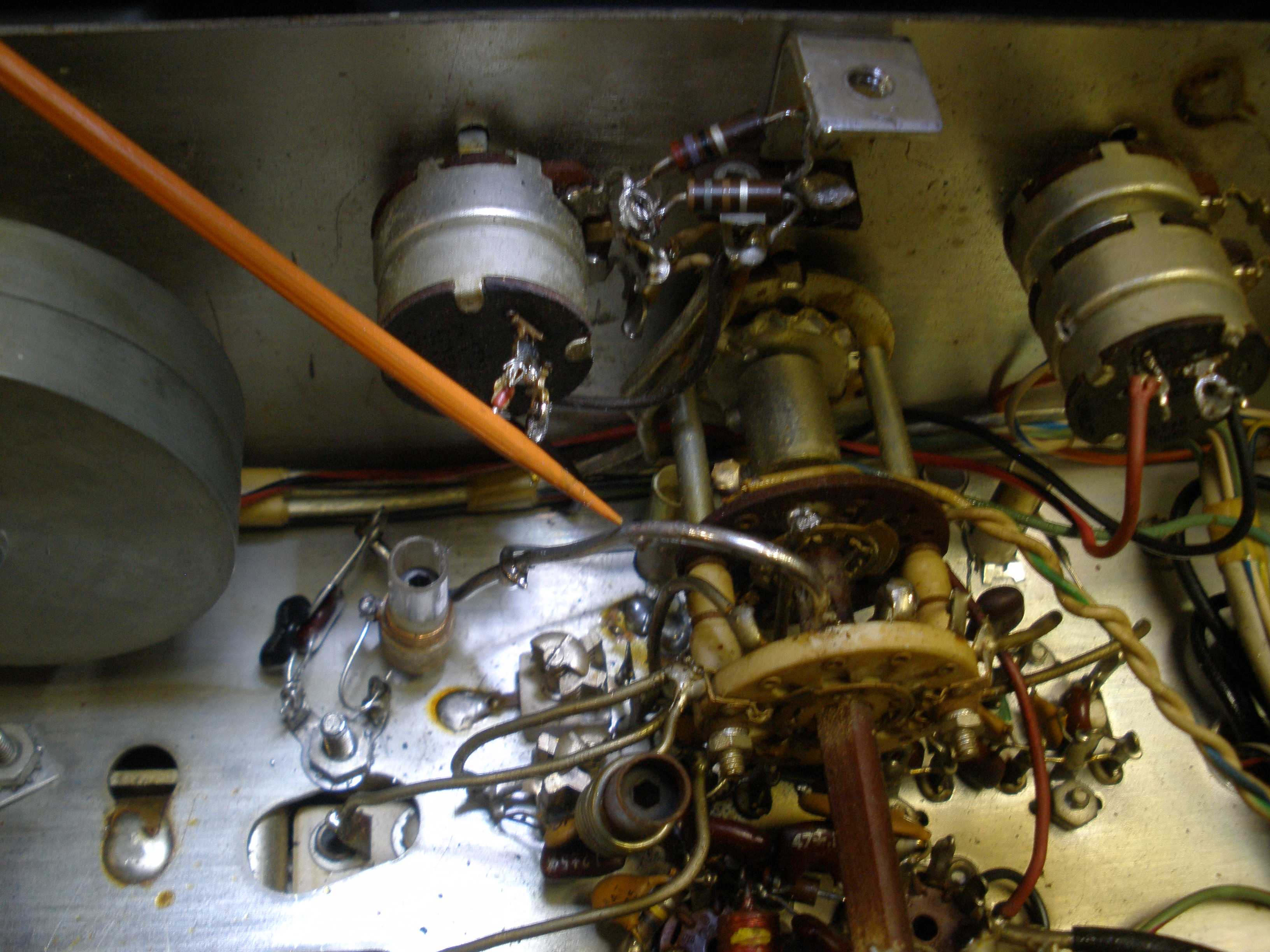
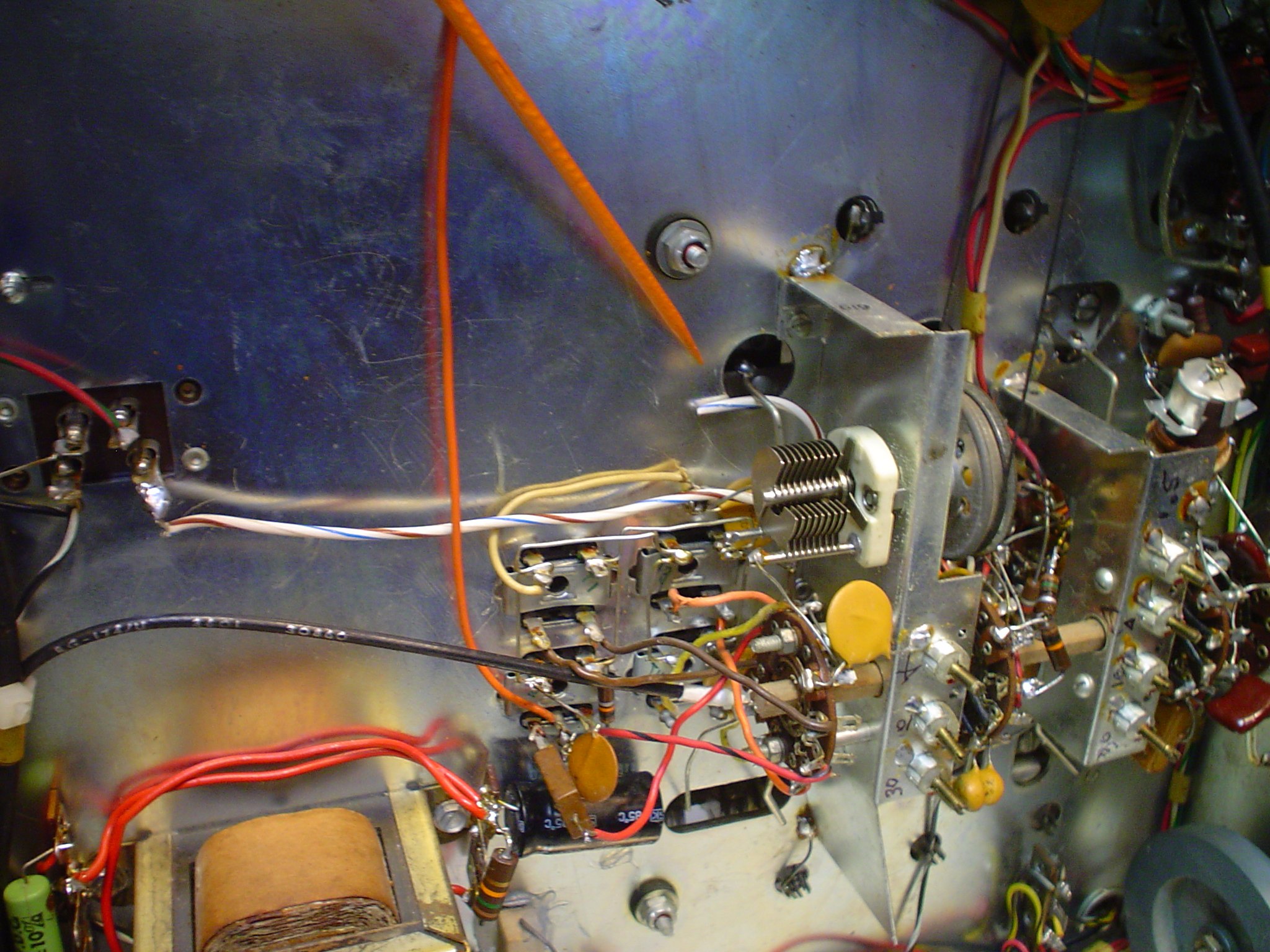
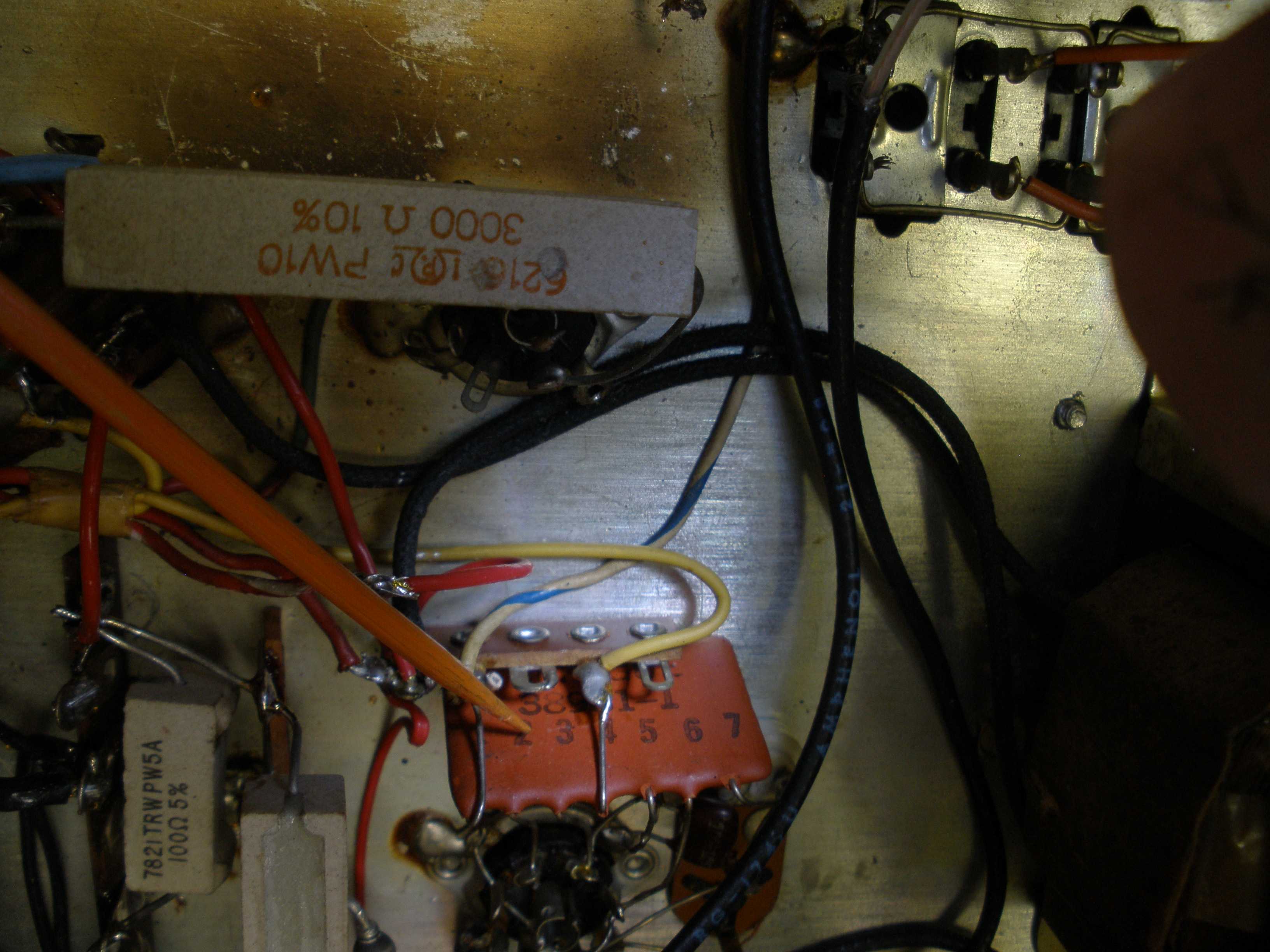
 From the Manual 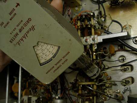 Grid Dip Meter - Testing 6 Meter Oscillator  Measure injection voltage HERE. I used a grid dip meter to get the oscillator on the right frequency; it was way off. I took a scope with a low capacitance (X10) probe and looked at pin 1 of the first 6BE6. The injection voltage was way low. This is an RF high frequency signal. Your scope should go to at least 30 MHz to work on the HF portion of this radio. The AC voltage should be somewhere between the readings of 20 and 10 meters.
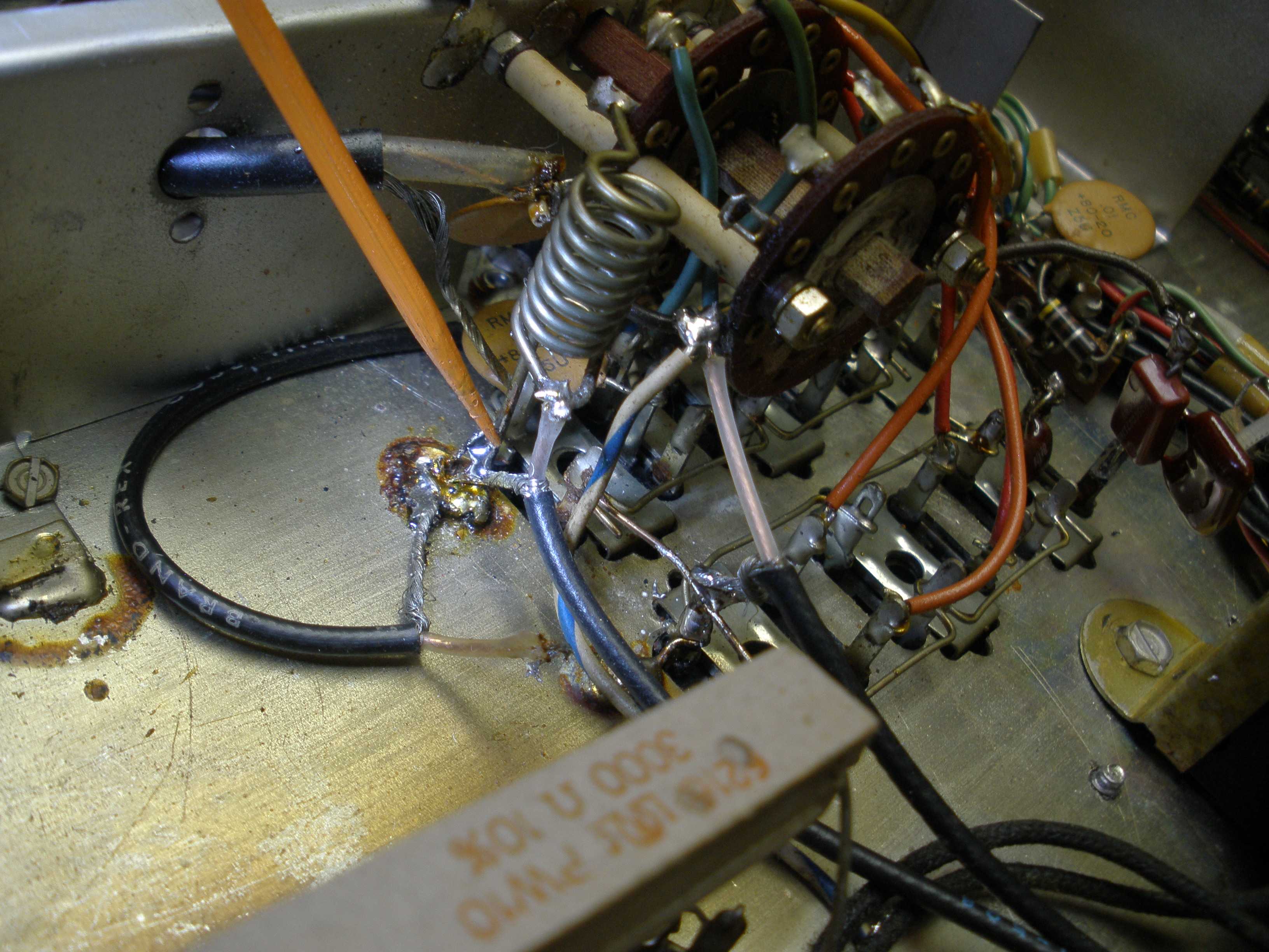
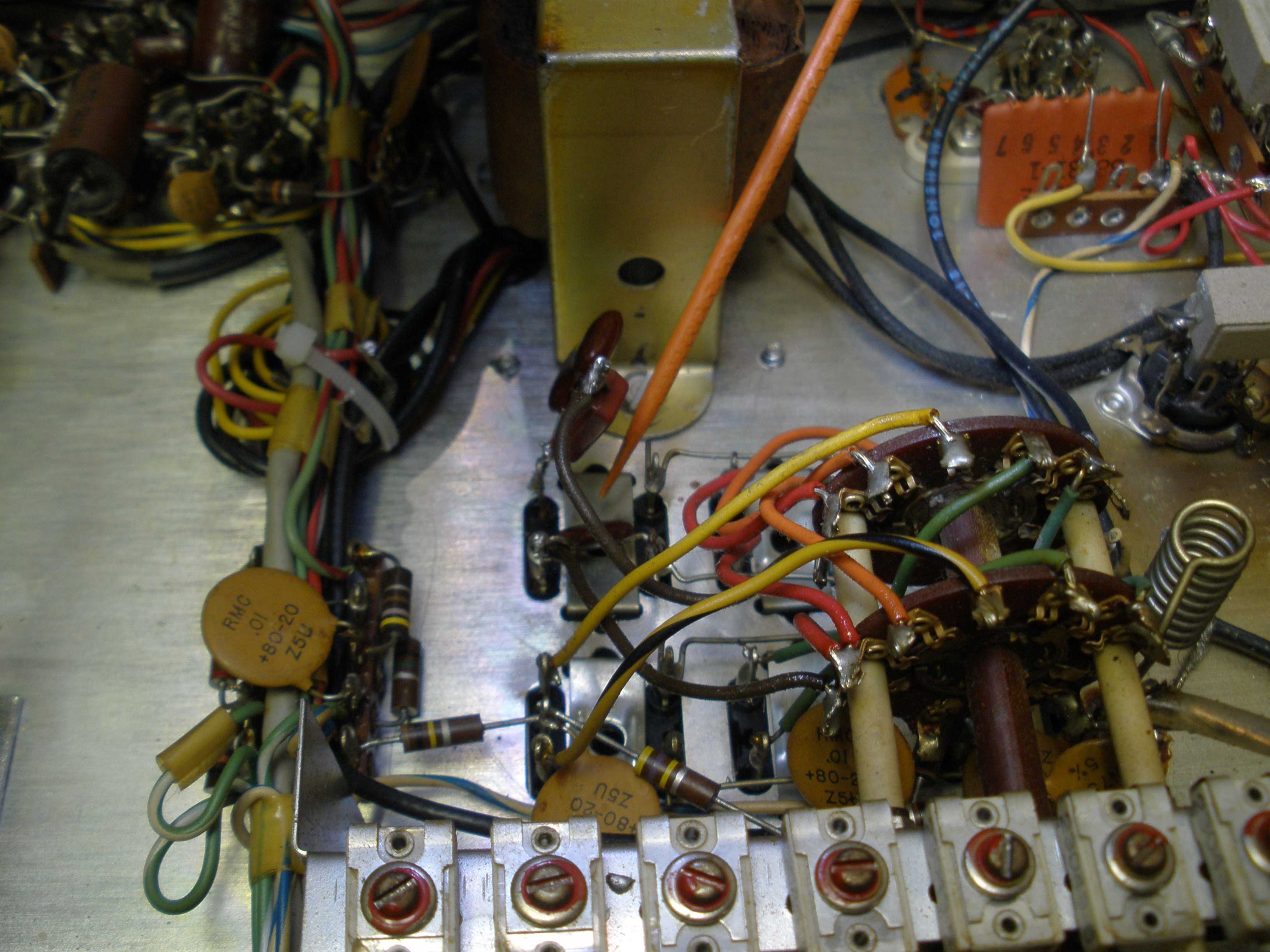
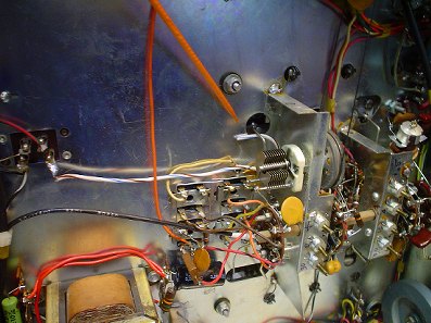
In desperation, I ripped out the whole cobbed in mess that was done by a previous owner. The ground return was to the terminal strip near the angle bracket that holds the cabinet screw in the bottom of the radio. This placed it too close to the bottom of the cabinet. If the oscillator was running, it stopped when I put it back in the cabinet. Maddening! I replaced the ceramic capacitors with new dipped mica caps that were about the right value, from the Hammarlund manual. I removed the compression trimmer and rewired to the original piston trimmer for the 15 meter band (they are very high Q). I replaced the coil with one using a core that seemed more appropriate for 21 MHz (better Q). This is similar to choosing the correct mix for your toroid inductors. I installed a ground lug near the tuning knob flywheel. I removed the flywheel temporarily to get more room to work. There is a screw that mounts the main tuning capacitor. I removed that nut, and installed two ground lugs there, at a 90 degree angle to each other. I used a piece of solid 12 guage house wire, tinned, to wire from the band switch contact to the new LC network. This is important for low wire inductance, especially important on the higher bands.
 Remove the flywheel temporarily. 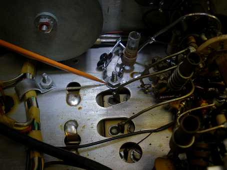 Install ground lugs here. 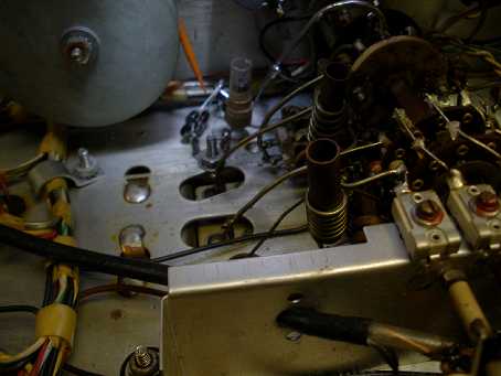 Use good quality capacitors. Use heavy tinned wire. I checked carefully for solder splashes and metal filings. Then powered on and checked with the grid dipper again, to get it near frequency. I double checked the 6BE6 pin 1 oscillator injection voltage. It was exactly between the voltages seen on 20 and 10 meters. Things were looking much better. I had to inject the RF signal at 21 MHz directly into the mixer grid coil, things were so far out of whack. I carefully walked adjustments closer to the right frequency. Then I injected signal on 21 MHz at the antenna coax receptacle and got the antenna RF input correct. A final pass for oscillator tracking to the tuning dial calibration, and the mixer and antenna coils and trimmer caps, using the manual procedure. Now the sensitivity on 15 meters was just as good as 20 or 10 meters, much better than 1 uV on AM.
 Always replace this capacitor. Do not forget to replace the cathode bypass on the 6AV6 in the HQ-170. This is also the filter for the bias for the delayed AGC. Squirrely things happen if this is bad. The original is 25 uF. I replaced it with a 47 uF. I may experiment with this later, to see if the AGC filtering is related to this capacitor. It might be a 500 uF could help stiffen the bias on the delayed AGC.
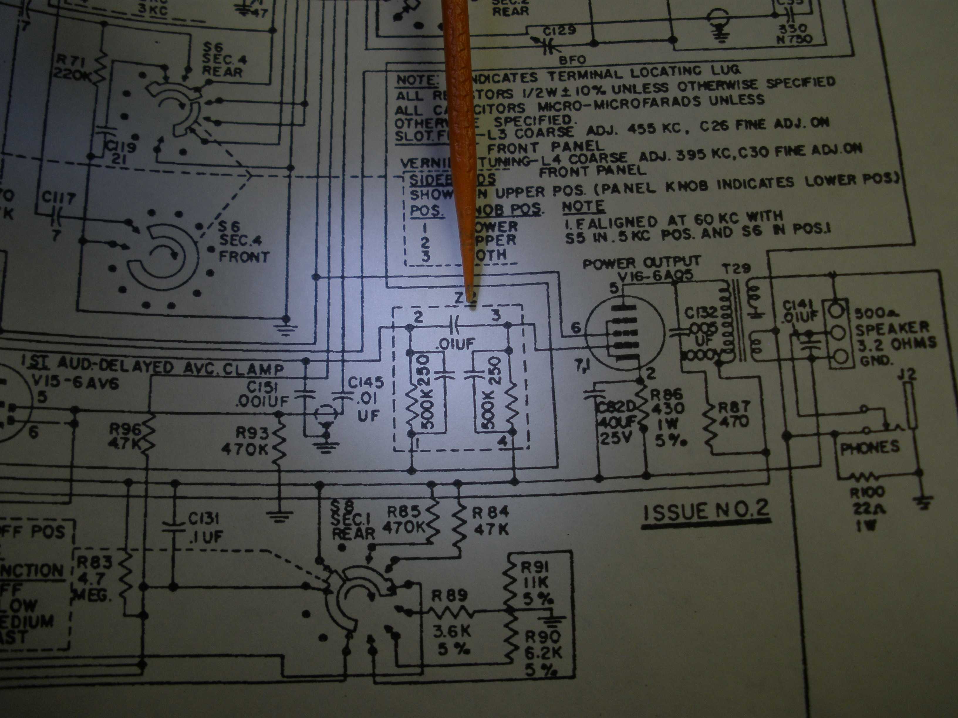
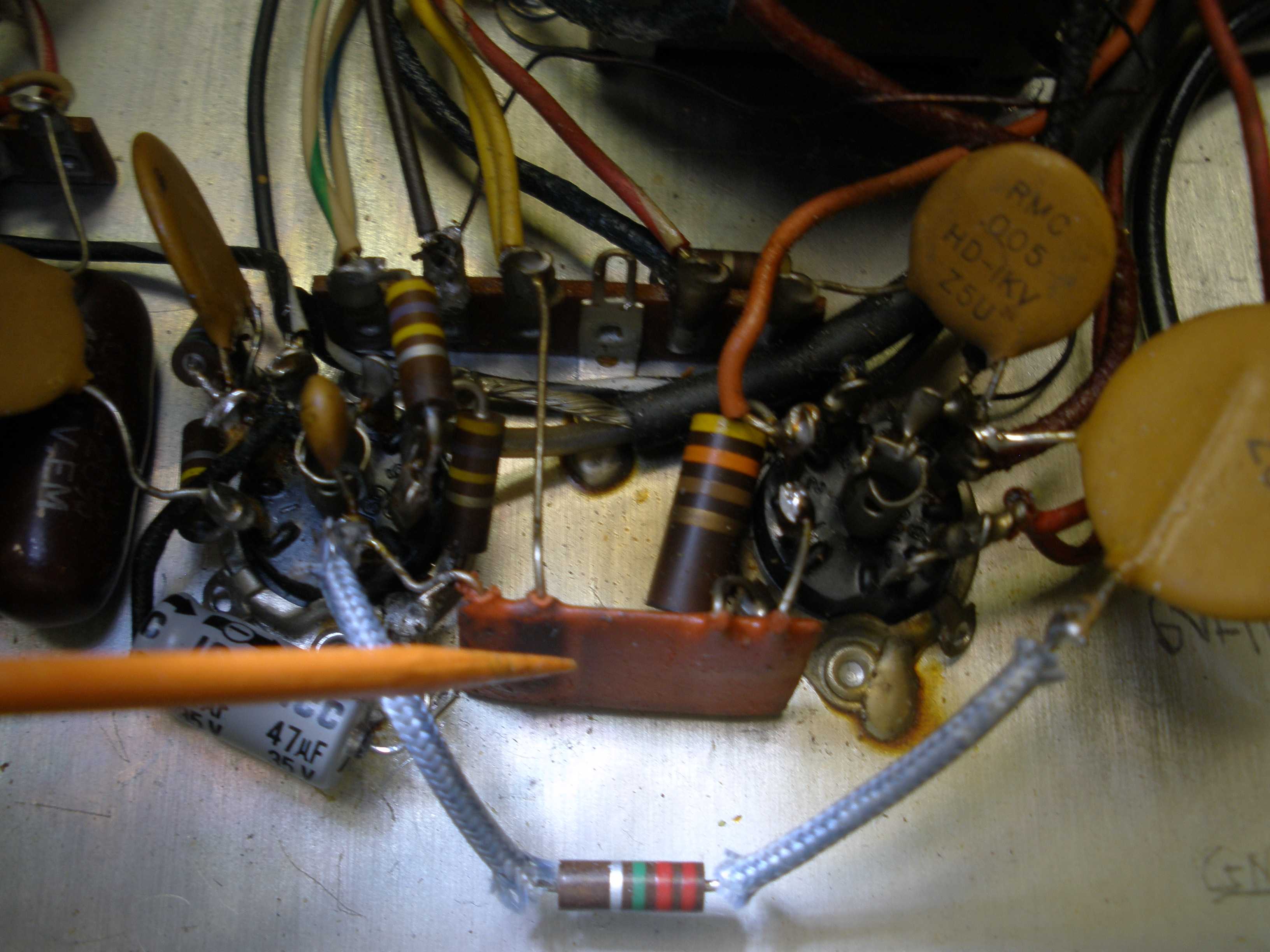
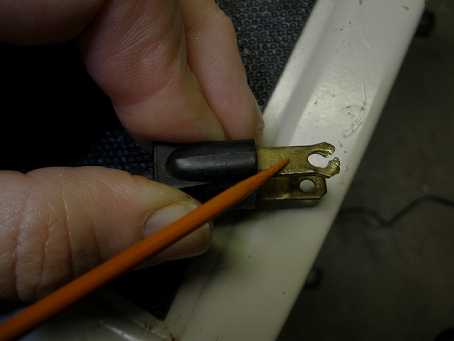
Speaking of AGC, there are two mods I referenced in the background and history discussion. I did not find EITHER of them improved this particular radio for its target user (AM). If you really want to mess with the AGC mods, the exact location to grab the connection is HERE:
 I could not successfully clean the gain pot for the S meter. It is the one on the left. The zero pot is OK. The original value was 1.5 K. It is connected as a variable resistor, not a potentiometer. So I installed a 2 K that I had in stock. I usually set the gain for near full scale when using the calibrator on 80 meters. The rule of thumb is that S9 is 50 uV. This is only useful in the laboratory, not connected to a real world antenna. What is the gain of the antenna? An S6 on a dipole reads S9 on a beam! In practice, this HQ-170 was 10 uV for S9 (typical), with compression of calibration near the upper end of the scale. This radio is so hot that when conditions are good, it pays to turn the RF gain down a bit. But in poor propagation conditions, this radio can hear better than most. By comparison, my NC-303 is just right on S9, and the S unit steps are about 6 dB, and the dB above S9 are accurate. What part of "relative" signal strength have people forgotten? Some radios are better than others in various areas.
Can capacitor Normally, I do not spend the extra money for the exact can electrolytic capacitor. The HQ-170 & HQ-180 can is about $35 each. It is crowded under the chassis. The existing wires may not reach. There are so many connections that a mix up might happen. It saves time to just cut the tabs off the old can. Do NOT unsolder any of the wires, you could confuse all the red wires. Leaving them on the old tab keeps them together. Solder the old wiring, tabs and all, onto the new can tabs. It is really worth the money to buy an original replica. Just be sure to label the old tab and its wiring with a geometric symbol (triangle, square, semicircle) and be sure it gets on the right tab of the new can.
The question of the audio mods always comes up. The HQ-170 and HQ-180 are "battle mode" radios for crowded band conditions. Radical audio mods will not significantly change the high frequency audio response. First, I do NOT recommend removal of the so called "couplates". This is a network of components on a thick film hybrid, sealed in potting, for easy assembly. The schematic shows two, one in the audio amp, one in the crystal calibrator. They are located as shown in the pictures. If you must, a larger coupling capacitor can be connected between the 6AV6 plate and the 6AQ5 grid, leaving the couplate in place. All I ever do to the 170 and 180 is to remove the "auto response" components located on the angle bracket that bolts the bottom of the cabinet onto the front panel. Then I install an inverse feed back network of a 0.02 uF capacitor and 1 Meg to 2.2 Meg in series with that. It goes between the 6AV6 plate and the 6AQ5 plate. This is full time, not part time, inverse feedback (unlike the "auto response"). It reduces distortion in the audio stages, improving clarity of reception. Play with the values to see what pleases you. Lower resistance means flatter frequency response at the expense of gain.
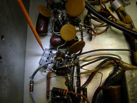
 Couplate cal oscillator 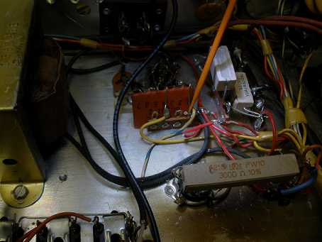 Couplate cal oscillator 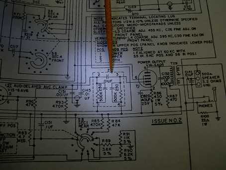 Couplate audio stage  Couplate audio stage 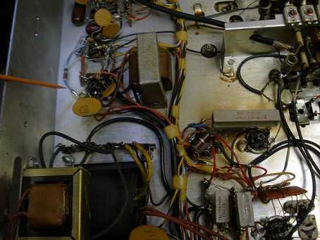 Inverse feedback network
Next↓Prev↑Top⇑PHOTOS OF HF ANTENNA WIRING:
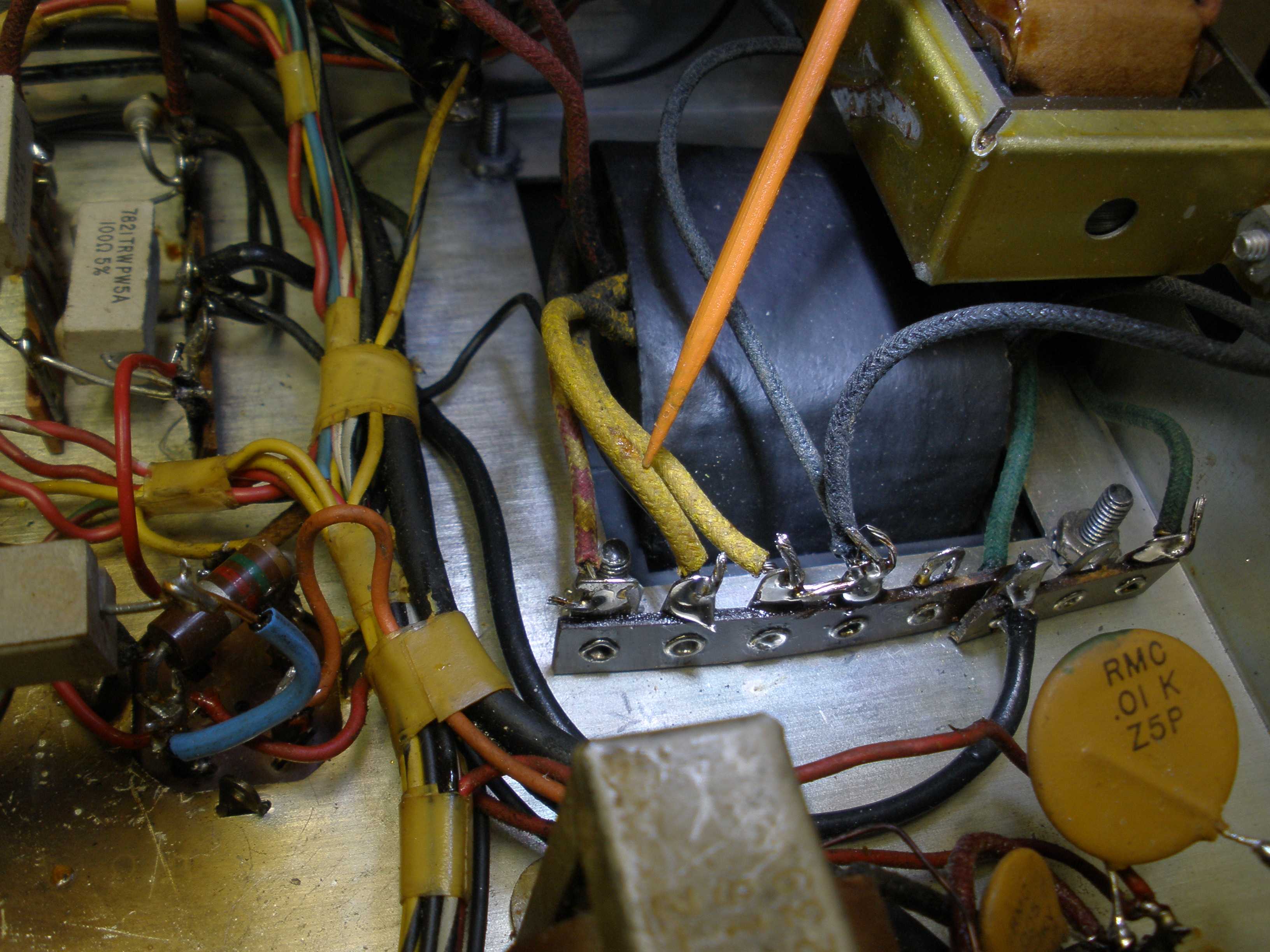
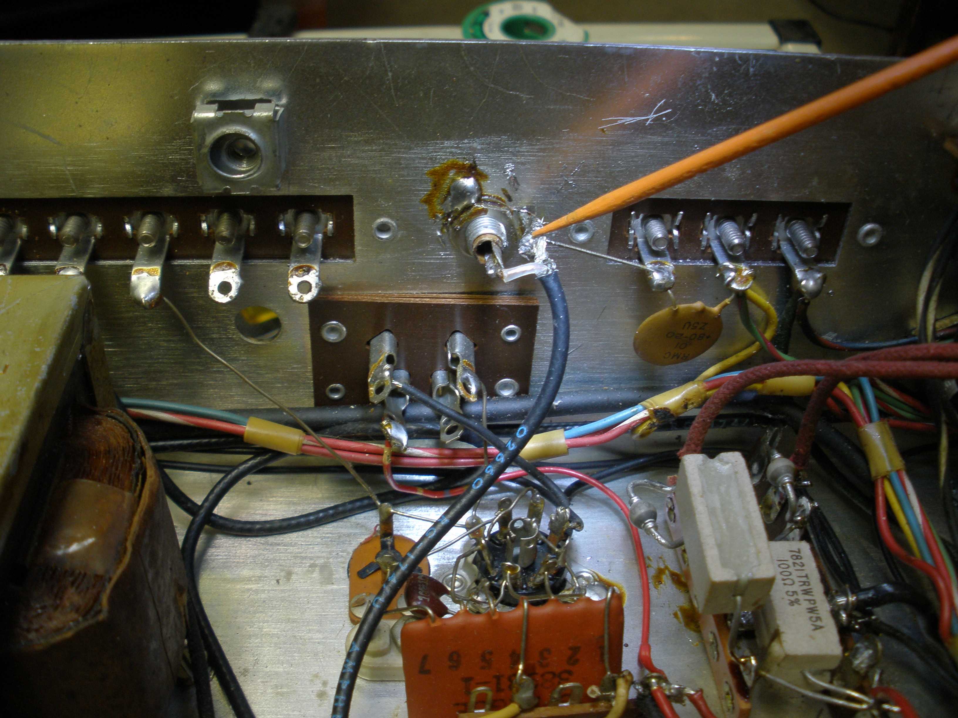
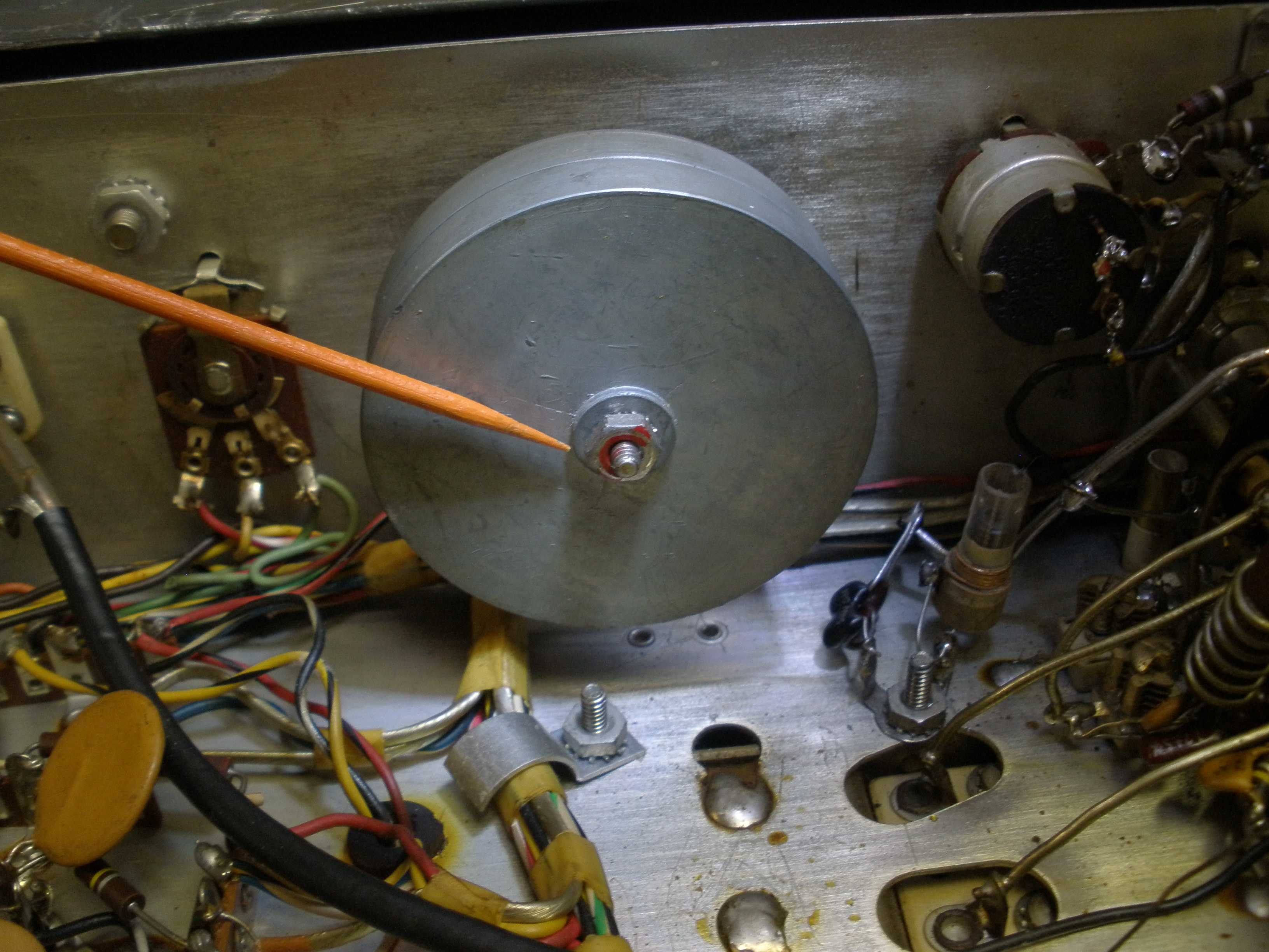
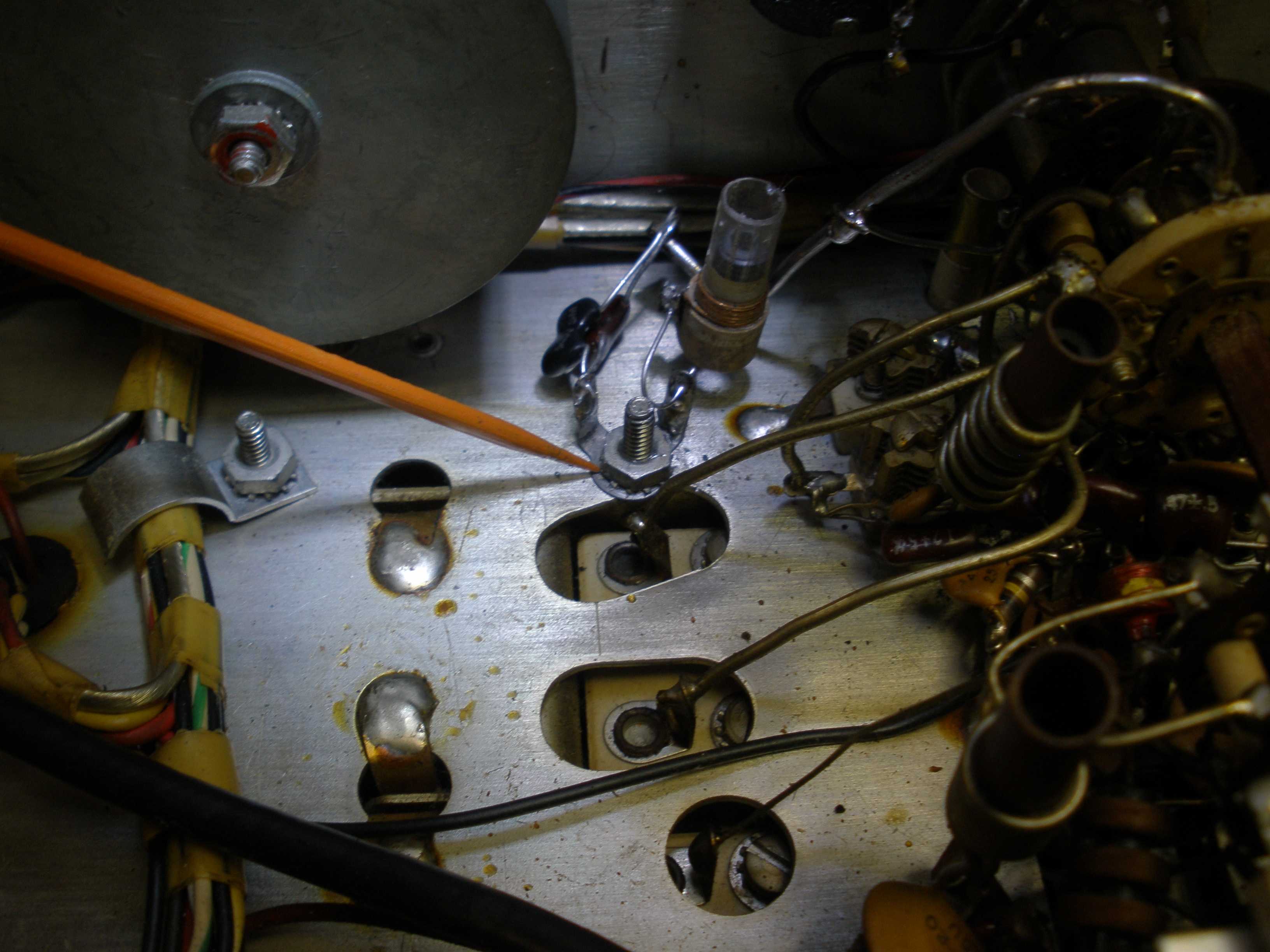
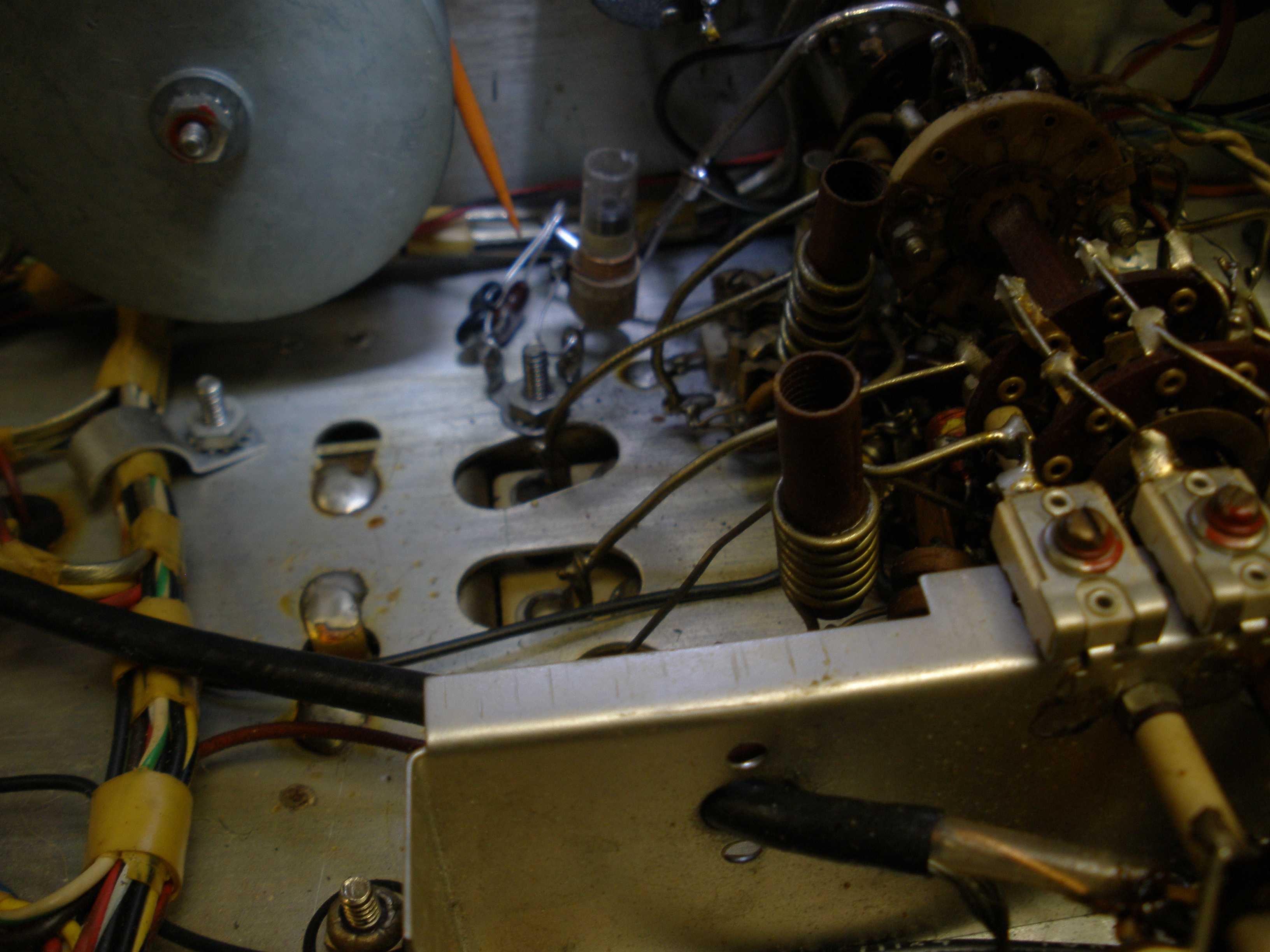
One item I address on the HQ-170 & HQ-180, after all other repairs, and before final precision alignment: the wiring to the antenna. Almost no one uses a true balanced 300 ohm antenna connection for their receiver these days. Open wire is popular still, but the antenna matching unit converts the balanced antenna to single ended 50 ohm coax for the transmitter and receiver. Unless you are a true old buzzard, running a pair of 812s push pull with plug in coils and a swinging link. Why is this important? The unfortunate choice later Hammarlund designers made to move the antenna trimmer capacitor physically to the front panel, instead of driving it from a dial cord and pulley made the radio prone to oscillation on higher frequencies. The sheet metal that mounted the capacitor was later shortened, reducing the shielding between the RF amplifier and the mixer. The twisted wires from the screws on the back panel contributed to the problem. It all added up to headaches. REMOVE ALL THIS CRAP. Replace it with good quality RG-174/U. The SEPARATE six meter input (RCA jack) might be replaced with a BNC or an F connector (for a 20 dB TV booster amp). Connect the HF antenna SO-239 directly to the switch as shown. It is easy to ground one side of the antenna coils at one point as shown in the following pictures. Keep all leads short outside the shield. Especially observe the lead dress for the 100 KHz crystal calibrator. Run this lead under everything else, and keep it right against the chassis. You could use RG-174/U for that too, if you want. But I worried about shorts to the B+ lead right next to the output on the couplate and terminal strip on the calibrator circuit. NOTE: There is no attempt to run the 6 meters off the calibrator, for reasons previously discussed.
 Remove this crap (on screw terminals) SO-239 HF coax drive  Connect coax to band switch 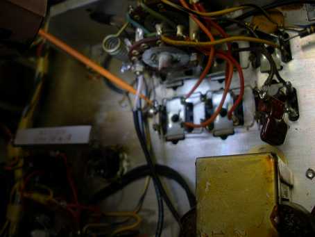 Ground HF ant coils here  Calibrator wiring 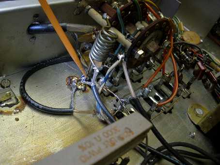 Calibrator wiring to band switch (blue white wire to the right of 6 meter coil)
Next↓Prev↑Top⇑PHOTOS OF SIX METER WIRING:
6 Meter Antenna Coil & New Coax New Coax to 6 Meter Antenna Jack 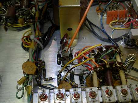 There is one more tweak to only the 160 meter antenna coils. This may help you out, if you have interference from very strong nearby AM broadcast stations that are the direct result of cross modulation from overload of the 6BZ6 RF stage. If it does not fix it, you will have to use a better BC band rejection filter. On 160, use a bridge or L meter to measure the input coil for that band after you have it aligned (about 6.8 uH). Insert a (1000 to 900 pF) mica capacitor in series with only the 160 antenna coil, that broadly resonates with that inductance. This inserts a series resonant circuit, giving a little more selectivity on 160. I have not seen this on any other bands, and it only happens when you are close to a BC transmitter, using a large antenna like the full wave loop which I have. (Make sure you are not hearing harmonics of the BC station by checking with another receiver.) If you are using a link coupled transmatch, you may not have to worry about this, because the extra tuned circuit reduces the BC station amplitude before it gets into the receiver. I also find that the range of the tuning slug and antenna trimmer on 160 only in 170A versions is not sufficient to get to resonance. I add a small fixed capacitor (20 pF or so) in parallel with the secondary of the 160 antenna coil if necessary to get to resonance, and the trimmer now is able to tune the whole band. In the A version, this is probably due to the removal of the third section (RF input tuning) of the main tuning capacitor. The two remaining sections are for mixer and oscillator, possibly to keep the price down. If the antenna trimmer is at its maximum or minimum on one end of the band, and the slug in the coil cannot bring it to resonance, try this tip on 160 meters only. This is a lot better than opening the antenna coil and breaking it instead of fixing the problem you started with.
Lastly, be sure you have read the Hammarlund tech notes and addressed any residual known problems. There are a number of Hammarlund acknowledged symptoms in this service bulletin:
http://www.hammarlund.info/hq178svc.pdf.
Finally, if you have the equipment, you may elect to do a sweep alignment. It is now time for you to watch the video from Pete, K7PP:
https://www.youtube.com/watch?v=sHJ5OlFtl78
This was probably the most challenging Hammarlund HQ series repair I have ever attempted. Even harder than the HQ-145 I did elsewhere on this site:
/Projects/Receivers/HammarlundHQ145.html
I hope the new owner enjoys this restored HQ-170A, which almost wound up on the scrap heap. NEVER throw an old radio away; the parts to resurrect this one came from an "organ donor". Make sure your broken gear goes to a scrounger like me, who uses the good parts from her "junkyard" to keep those filaments lit. I used some knobs off the organ donor to get this radio back to original looks. Appearance is an important final touch, but do not start there in the repair process. I do not get into a lot of chassis polishing until I have a good working radio. You can disturb things with chemicals and never find out where you went wrong.
FINAL PRE-SHIP TEST: The Hammarlund spec for sensitivity is 1 uV on the HF bands. You should settle for no less. The 160 meter sensitivity is not quite as good as the rest, but typically the ambient noise on that band will not be low enough to use more gain. It still is better than the 1 uV Hammarlund AM sensitivity spec. The CW and SSB sensitivity is much better than that, on a par with most good modern radios. Here is what I got at final test, in the cabinet.
| BAND | SENSITIVITY uV |
|---|
| 160 | <0.7 |
| 80 | <0.3 |
| 40 | <0.3 |
| 20 | <0.3 |
| 15 | <0.3 |
| 10 | <0.3 |
| 6 | ~150 |
Which is about as good as you can get 6 meters, without the "VHF" option, which uses the 2 meter converter for a 6 meter preamp. This radio did NOT oscillate on 6 meters. Nice surprise. Sometimes you can select 6BZ6s and find one that behaves. Often a tube that will test good just will not work right. Hammarlund inserted low ohm resistors in the leads of the tube to stabilize it. The production differences in tubes will sometimes put the characteristics out of the range of operation of such experimentally determined components. The 6BZ6 is a good low noise tube, good transconductance, but it is known to be squirrely. There are substitutes, but many will not deliver the noise figure you need for 15 and 10 meters, especially 6 meters. It is better to stick with the 6BZ6, if you have a working radio with good measured sensitivity. A signal generator with a calibrated output level will tell you if you have met the published spec for sensitivity. When you have met the spec, stop. Do not be of the school that "if it ain't broke, fix it till it is". The 6 meters antenna connection is on a separate RCA jack on the back of the radio. You can replace that with a BNC if you want. I would also suggest an F connector for it. Then you could get a small solid state TV booster amp. A good low noise 20 dB TV amp would get you down to better than 10 uV or so, which is useable with a good antenna on a local classic AM QSO on 50.4 MHz. The 6BE6 mixer is working way above its pay grade on 6 meters; this is as good as it gets. If you have a working 2 meter converter installed, that provides an internal 6 meter preamp. The 2 meter converter works pretty good, for its day. It uses Nuvistor tubes, which have excellent gain and low noise. An external power supply for the internal 2 meter converter could have been used for a fix in this case, but I did not go that far. There are better options these days. But if you are into vintage 2 meter AM, the HQ-170 could be YOUR radio. There are circuits that use the 455 KHz output for an external FM converter.
Proper alignment of the 60 KHz Low IF is essential to distortion free AM and SSB reception. K7PP has a performance test for the HQ-170 and HQ-180 that will reveal if the IF even needs service. His advice on the Low IF alignment is this: "If it passes this test, for God's sake, leave it alone."
https://www.youtube.com/watch?v=4l1hWNvPe2g
Perform this test FIRST BEFORE you attempt alignment. Note that the setting "BOTH" and "0.5 KHz" does NOT WORK as you might anticipate. That is why alignment instructions tell you to align it in USB and 0.5 KHz.
IF you choose to align your HQ-170 or HQ-180, a stable accurate RF generator is mandatory. Use an accurate frequency counter to set its frequency exactly to the IF frequency you are aligning. This will allow you to use the procedure shown in the manual.
SOME manuals in circulation have errors, as K7PP points out in this video. https://www.youtube.com/watch?v=1iworgjpp18 Watch this video before attempting IF alignment. Observe the quality of his test gear, and if yours is not on par with that, you should not attempt alignment. Minor errors in frequency WILL have adverse effects on performance. Some advocate sweep alignment, and if you have the equipment and skill set, that is the best method. Old TV sweep generators are NOT suitable. Even some newer gear intended for FM tuners will not have a stable narrow enough sweep to do the job. K7PP demonstrates proper sweep alignment of the HQ-170 and HQ-180 Low IF in this video; observe the types of generators he uses if you are considering this method. https://www.youtube.com/watch?v=sHJ5OlFtl78 Hammarlund does not give a procedure for aligning the High IF of 3.035 KHz for a good reason. I strongly advise you to leave it alone. DO NOT TOUCH T2 and C79 in the HQ-180. The HQ-170 does not have a crystal filter in the High IF, so its OK to use the Hammarlund procedure.
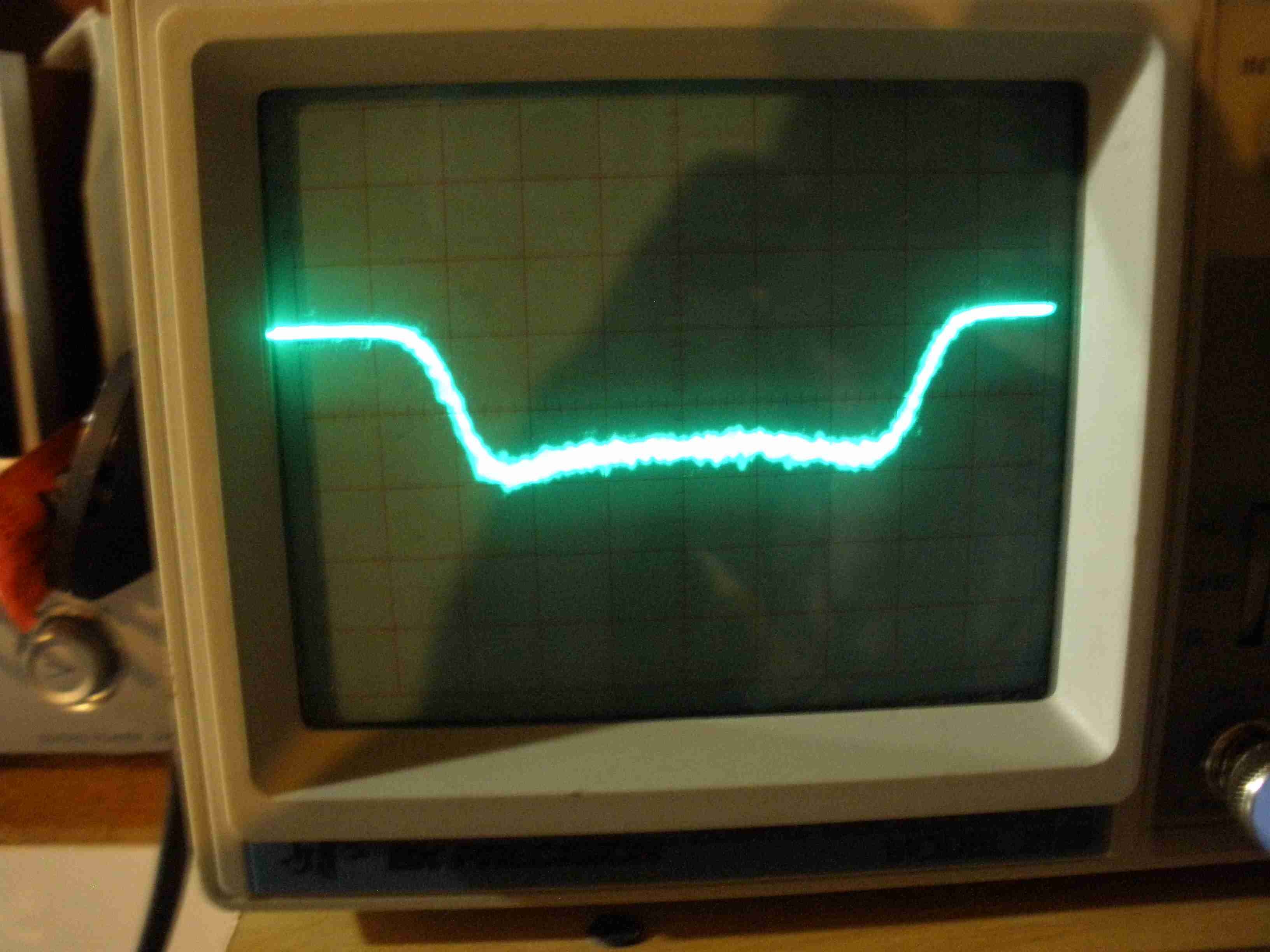
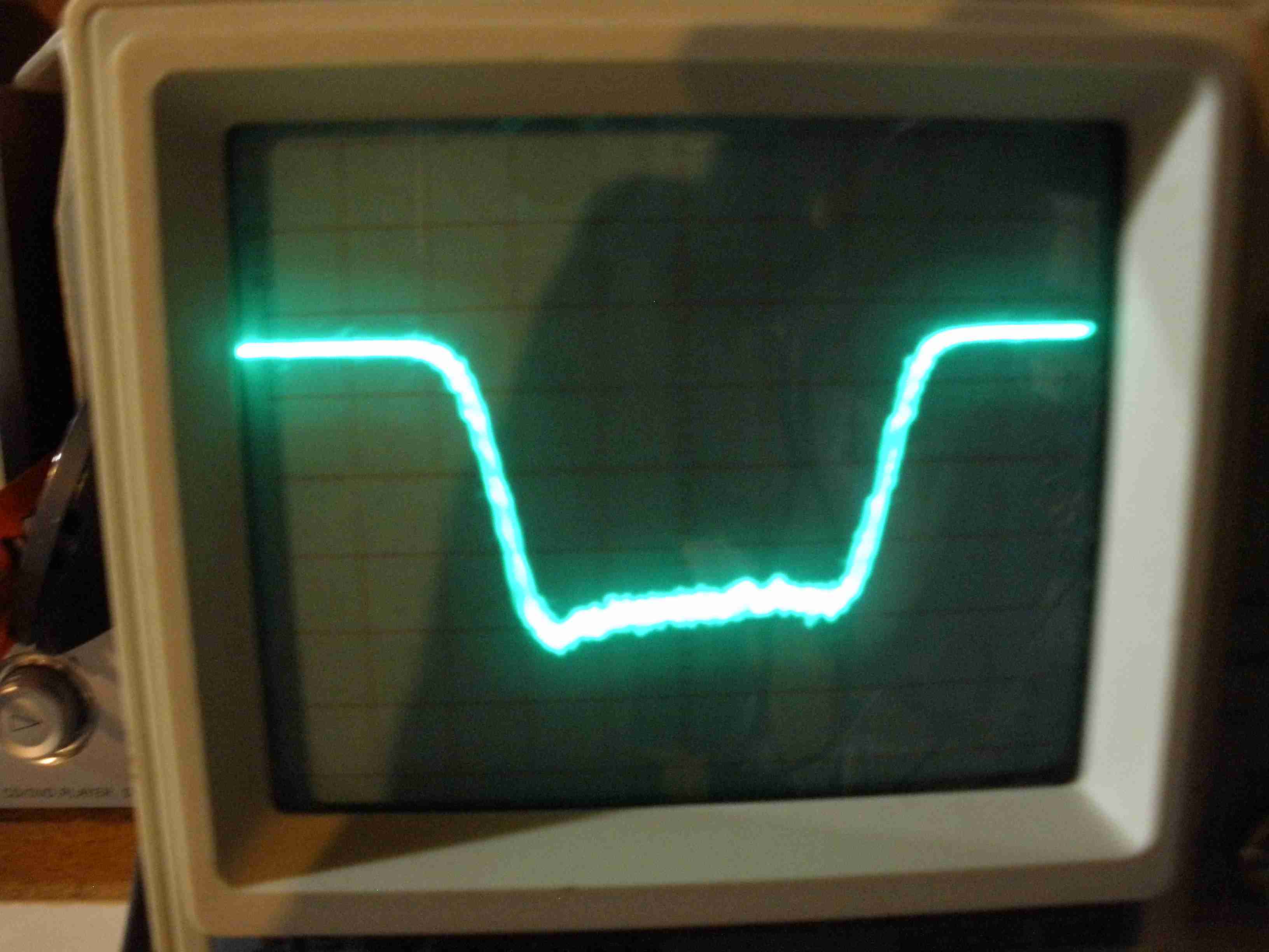
A lot of information can come from setting the sideband selector and band width selector to various values and rocking the band spread tuning back and forth across a S6 carrier from a signal generator on a lower frequency in the 160 meter band on the HQ-170, and 2.1 MHz on the HQ-180. If the s meter deflection has a clean smooth response as you tune through the carrier slowly, the IF is in good shape. Often after alignment, the 3 KHz BOTH position will have two peaks at the upper and lower edges of the band pass. These can be eliminated by careful adjustment of T8 and T9. Moving those peaks inward slightly towards the center gives a smooth curve which gives good low distortion AM reception. I used this method on a test receiver and provide below the sweep generator results for the BOTH and 1, 2, and 3 KHz settings. For these tests, I used an HP 3311 sine, triangle, square wave function generator with an external VCO input which allowed the external generator to move the main generator's frequency above and below the IF frequency. Its a cheaper alternative, but most of these generators only go up to 100 KHz.
 3 KHz, BOTH (6 KHz TOTAL)  2 KHz, BOTH (4 KHz TOTAL) 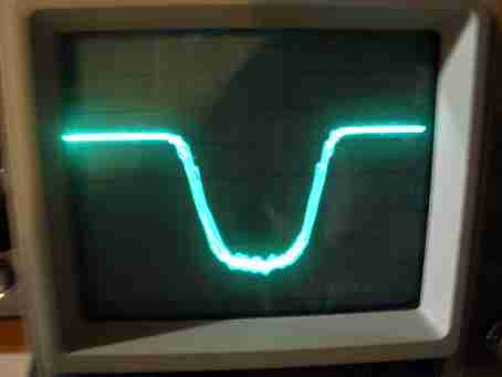 1 KHz, BOTH (2 KHz TOTAL) The 455 KHz IF is sufficiently broad that the IF alignment described in the manual is all that is necessary. Capacitors C 153, 154, and 155 are installed on the plate and grid side of the 455 KHz IF transformer to give a wider nose on the response curve.
The 3.035 KHz IF has about 7 - 8 KHz band width. It drops off quite sharply at the edges, giving a fine roofing filter to the frequencies above 7.85 MHz. This enhances adjacent channel rejection from strong signals which could overload a receiver without it. Its one of the reasons the HQ-180 costs substantially more than the HQ-170 ham band only receiver. A similar method can be applied to the 3.035 KHz IF but only mess with this if the response is badly wrong due to component replacement or previous tampering. I am not going into details on this topic, because most hams do not possess the proper equipment to perform the adjustments properly. That is probably the reason Hammarlund chose not to include it in their service manual.
It is still a good idea to use an audio attenuator for headphones on this radio, since the direct audio speaker output is available on the front panel. This was designed with 2000 Ohm headsets in mind. I like Radio Shack light weight low-Z monaural full frequency response headsets for AM use, so I can monitor the outgoing transmissions. But I use a separate headphone breakout box for multiple headsets that I constructed for field day with individual volume controls (one for me, one for my logger). Why not just put a new headphone jack with switching contacts and a resistor to fix this? You could. The way I use my station, I share the excellent Hammarlund speaker with the radios on my operating position. I do not want to have to pull the radio out to connect it on the back, so I plug the speaker into the headphone jack of the radio I am using at the time. An attenuator in the headphone jack would prevent that desirable feature.
- HQ-180 RESTORATION, ALIGNMENT OF 3.035 MHZ CRYSTAL FILTER & SWEEP ALIGNMENT TRICKS
- K7PP VIDEOS. PETE IS AN ACE, I LOVE HIS WORK. CHECK THEM OUT!
I MAY INDEX SOME OF THEM, SO I CAN FIND THE INFORMATION I WANT QUICKLY
- HERE IS A SAMPLE VIDEO TO GET YOU STARTED: HQ-180 GREMLINS!
https://www.youtube.com/watch?v=x0T39QzXtmA
|